Molex Mini-Fit Jr. (MX4.2) vs KONNRA KR4200: Two Specifications, Four Wire Windows, and the 9A Tier That Matches the Original
Quick answer: The Molex Mini-Fit Jr. is a 4.20mm pitch crimp connector system for wire-to-board and wire-to-wire use — the family Asia's catalogue shorthand calls MX4.2 — built around the female crimp terminal 5556, the receptacle housing 5557, the male crimp terminal 5558 and the plug housing 5559, with the vertical header 5566 and the right angle header 5569 on the board side. Molex rates it 600V AC/DC in its UL and CSA columns and 250V in its IEC column, and publishes a 56-cell current table whose maximum is 9A at AWG #16 or #18 in a two- or three-circuit brass connector.
The KONNRA KR4200 cross-references that family, and the single most important thing to know about it is that it is documented twice per interface with two different ratings: a 5A (20AWG) tier over 20# to 24# with insulation 1.10 to 1.80mm, and a 9A (16AWG) tier over 16# to 20# with insulation 3.10mm maximum. The 9A tier is the one that matches the original's maximum, and its 3.10mm ceiling is the same figure Molex publishes for 18 to 24 AWG. Three limits sit beside that. At 20 AWG our single published figure is 5A against the original's 7A for brass and 6A for phosphor bronze; neither of our tiers covers 26 or 28 AWG; and the 5A tier's 1.80mm insulation ceiling is 1.30mm tighter than the original's 3.10mm for 18 to 24 AWG. Our dielectric test level is 1,500V AC for one minute against the original's 2,200V AC for one minute, which is exactly what the original's own formula yields at 600V. And the original's temperature ceiling depends on the contact base metal (brass +80°C, phosphor bronze +105°C) while we publish one figure for a terminal whose material section leaves the choice open.
I work on connector and harness programmes at KONNRA, so treat that disclosure as read. Where two documents disagree, both figures are printed rather than averaged or reconciled — inside one company's document set as much as across the two.
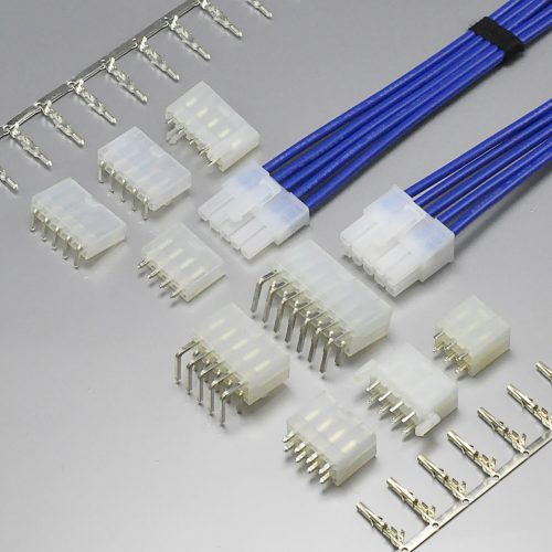
KONNRA KR4200 series Mini-Fit 4.2 wire-to-board connector
👉 KR4200 cross-reference for the Molex Mini-Fit Jr. 5556/5557/5558/5559 series · KR4200 female terminal, wire-to-board · Wire-to-board connector range · Wire-to-wire connector range
What the Molex Mini-Fit Jr. Actually Is
Mini-Fit Jr. is one of the few connector families whose own specification states its scope in a sentence a designer can design against without opening a drawing. Molex's current product specification opens with this:
"the MINI-FIT JR. 4.20 mm (.165 inch) centerline (pitch) printed circuit board (PCB) connector series with Tin or 30µ" Gold plating, and the MINI-FIT JR. connector series terminated with 16 to 28 AWG stranded, copper wire using Crimp technology with Tin or 30µ" Gold plating."
Four things are fixed by that sentence: the pitch is 4.20mm, published with its imperial equivalent of .165 inch; the family is a crimp family; the plating choice is tin or 30µ" gold, and the gold figure governs several mechanical and environmental rows later in the document; and the wire range is stated as a whole, 16 to 28 AWG stranded, copper. The architecture is the usual three-part wire-to-board system and the usual two-part wire-to-wire system, and the KR4200 is documented for both interfaces separately and with two ratings per interface. In the wire-to-wire configuration both ends of the cable run carry a crimp terminal inside a housing, and the two housings latch to each other; in the wire-to-board configuration the wire half is the same and the board half is a header soldered to the PCB, straight or right angle.
The series map, in the original's own part numbers
| Interface | Function | Molex series |
|---|---|---|
| Wire-to-wire | Female crimp terminal | 5556 |
| Wire-to-wire | Receptacle housing | 5557 |
| Wire-to-wire | Male crimp terminal | 5558 |
| Wire-to-wire | Plug housing | 5559 |
| Wire-to-wire | Plug housing | 45776 |
| Wire-to-wire | Receptacle housings | 46992 / 46994 |
| Wire-to-wire | Plug housings | 46993 / 172646 |
| Wire-to-board | Female crimp terminal | 5556 |
| Wire-to-board | Receptacle housing | 5557 |
| Wire-to-board | Vertical header | 5566 |
| Wire-to-board | Right angle header | 5569 |
| Wire-to-board | Receptacle housings | 46992 / 46994 |
| Wire-to-board | Vertical headers | 172447 / 172647 |
| Wire-to-board | Right angle headers | 172448 / 172648 |
Three points follow. The female terminal 5556 and the receptacle housing 5557 are shared between the two interfaces and the male side is not, so a cross-reference that pairs a wire-to-board request against a male terminal and a plug housing is answering a wire-to-wire question. The four digits the market uses as shorthand describe only the wire half, so a complete wire-to-board bill of materials also needs 5566 or 5569, or one of the glow-capable headers. And the -210 suffix denotes the higher flammability grade — 5557-NR is UL 94V-2 and 5557-NR-210 is UL 94V-0 — while the P and P1 suffixes on the plug housings describe the presence or absence of wings, a distinction our cross-list gets wrong in two places.
What the original publishes about its wire side
Molex publishes three applicable-wire windows by terminal, not one window for the family:
| Applicable wires (Molex, current specification) | Insulation |
|---|---|
| 16 AWG standard copper | 3.15 mm maximum |
| 18–24 AWG standard copper | 3.10 mm maximum |
| 22–28 AWG standard copper | 1.80 mm maximum |
The shape of that table is the thing to notice: three overlapping bands whose insulation ceilings step down as the conductor gets finer. A 20 AWG wire falls inside two of the three bands, so a 20 AWG wire with 2.5mm of insulation is acceptable under the 18–24 AWG, 3.10mm window even though it would not be acceptable under the 22–28 AWG, 1.80mm window. The band is selected by the terminal, and the terminal is selected by the wire, so the two are not independent choices.
The original also publishes a wire pullout force (axial, at 25 ± 6 mm per minute, without influence from the insulation crimp) per gauge as a minimum — 68.4 N at 16 AWG, 88.0 N at 18 AWG, 58.7 N at 20 AWG, 39.1 N at 22 AWG, 29.3 N at 24 AWG, 19.6 N at 26 AWG and 9.8 N at 28 AWG — with the non-monotonic shape printed as such, since the 18 AWG figure is the highest in the table rather than the 16 AWG one, and the caveat that governs its use: "Wire pullout force is applicator dependent."
The wire side is also the subject of the second Molex document, which is older and narrower: a variant-specific specification for a flanged right angle version of the family, dated 2007, listing terminal (AWG #18 to #24) 5556APBT(L), housing in UL 94V-2 as 5557-NR and in UL 94V-0 as 5557-NR-210, and header assembly in UL 94V-2 as 5569-NB1 and in UL 94V-0 as 5569-NB1-210. It names an insulation window of 1.3mm to 3.1mm outside diameter, a rated voltage of 600V AC(rms)/DC, a temperature range of −40 to +105°C including terminal temperature rise, a contact resistance of 10 milliohm maximum measured at 20mV maximum and 10mA, an insulation resistance of 1000 megohm minimum at 500V DC, and a dielectric strength of 1500V AC(rms) for one minute.
That last figure is the reason this article prints two dielectric values for the original rather than one. The older document says 1,500V AC for one minute; the current specification says 2,200 VAC for one minute. Both are Molex figures, both are on the same 4.20mm family, and they differ by 700V. They are not reconciled here, because the documents themselves do not reconcile them.
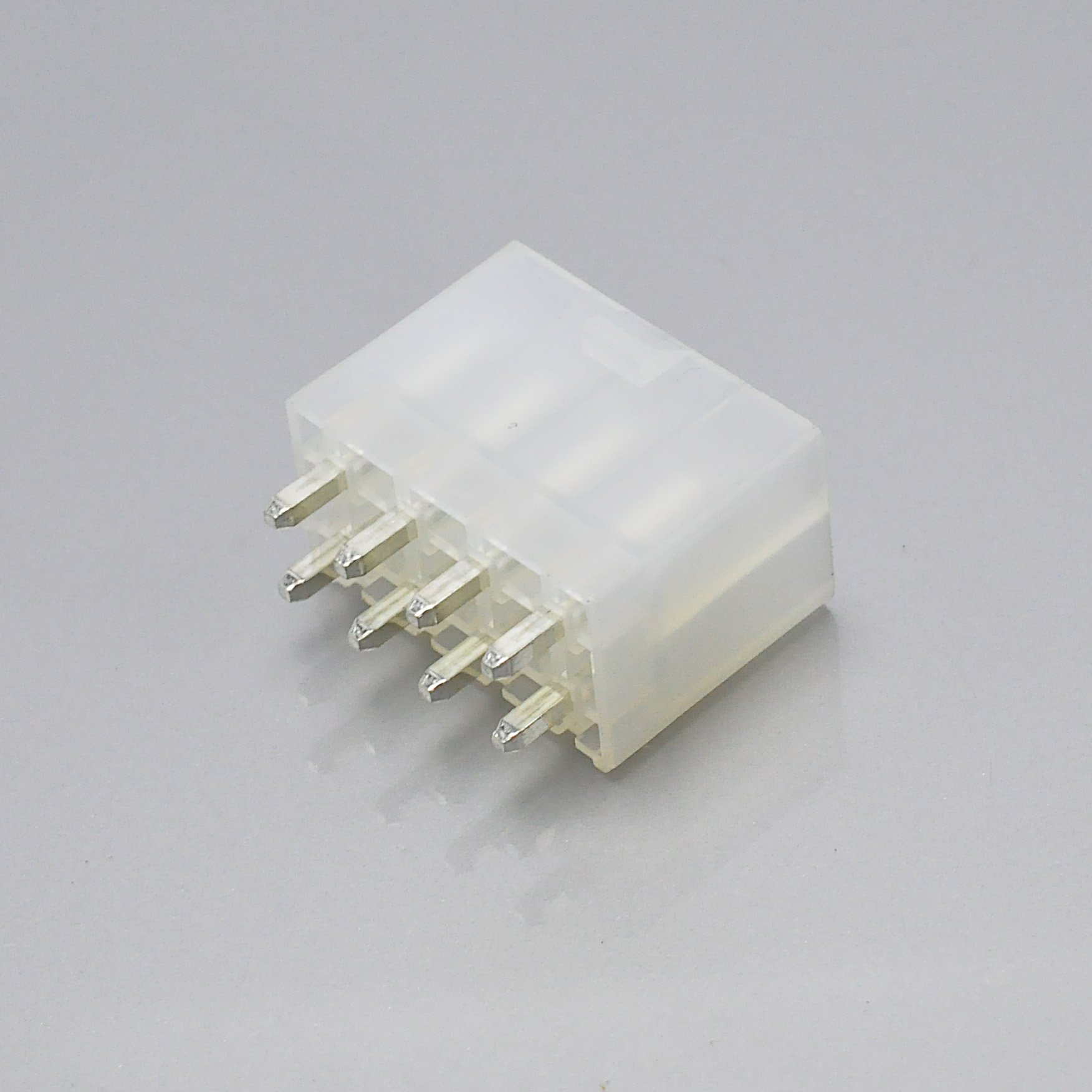
KONNRA KR4200 series dual row straight wafer, 4.20mm board header
The Ratings Side by Side
The whole comparison in one place. Where the original disagrees with itself, both of its values are printed in the same cell. Read the current row first, then the insulation row, then the temperature row: those three carry the whole argument of this article, and they are where a buyer who reads only one document from each side is most likely to reach a conclusion the other document contradicts.
| Row | Molex Mini-Fit Jr. | KONNRA KR4200 | Verdict |
|---|---|---|---|
| Pitch | 4.20mm (.165 inch) | 4.20mm | Level |
| Rated voltage | 600V AC/DC (UL and CSA columns); IEC column 250V | 600V AC/DC (all four specifications) | Level against UL/CSA; not against the IEC column |
| Voltage basis | UL 1977 | Not stated | Original publishes its basis |
| Current | 56 cells: 2 base metals × 7 gauges × 4 circuit bands; maximum 9A | Two tiers: 5A (20AWG) and 9A (16AWG) | The 9A tier matches the maximum |
| Wire range | 16–28 AWG | 20#–24# (5A tier) or 16#–20# (9A tier) | Partial overlap; no 26 or 28 AWG |
| Insulation windows | 3.15mm / 3.10mm / 1.80mm (three windows) | 1.10–1.80mm (5A tier) or 3.10mm Max. (9A tier) | The 9A ceiling equals the original's 18–24 figure |
| Operating temperature | −40 to +80°C brass; −40 to +105°C phosphor bronze | −40 to +105°C | Matches phosphor bronze only |
| Contact resistance, initial | 10 milliohms maximum | 10 milliohms Max. (dry circuit 20mV/100mA, EIA-364-23C) | Level |
| Insulation resistance | 1000 Megohms minimum at 500 VDC | 1000 Megohms Min. at 500V DC | Level |
| Dielectric withstanding voltage | 2,200 VAC for 1 minute (current spec); 1,500V AC(rms) for 1 minute (older variant spec) | 1500V AC for 1 minute | 700V below the current original; level with the older |
| Durability | 30 cycles → 20 mΩ max change | 30 cycles → 20 milliohms Max. | Level |
| Temperature rise basis | +30°C maximum | 30 Max. | Level |
| Heat resistance | 96 hours at 105 ± 2°C | 105 ± 2°C, 96 hours | Level |
| Cold resistance | 96 hours at −40 ± 3°C | −40 ± 2°C, 96 hours | Level figure, different tolerance band |
| Thermal shock | 5 cycles between −55 and 105°C | 5 cycles −40/+105°C | Different cold end |
| Terminal insertion force | 15.0 N maximum | 1.5 kgf (14.7 N) Max. | Within about 2% |
| Terminal retention force | 30 N minimum | 3.0 kgf (29.4 N) Min. | Within about 2% |
| Pin retention force | 9.81 N minimum | 1.0 kgf (9.8 N) Min. | Within about 2% |
| Per-circuit insertion | 14.7 N maximum | 1.50 kgf (14.71 N) per circuit maximum | Within 0.01 N |
| Per-circuit withdrawal | 0.5 N minimum | 0.10 kgf (0.98 N) per circuit minimum at first mate | Ours is about double |
| Housing material | Not stated in the electrical rows quoted here | PA66 UL94 V-0 or V-2 | — |
| Terminal material | Split by base metal throughout | Phosphor Bronze/Brass Tin Plated Over Nickel | Left open |
| Agency files | UL E29179 · CSA LR 19980 · IEC 61984 | UL E482542 | Original publishes more |
| Glow wire | Named series, EN 60695-2-11 / IEC 60695-2-11, 750°C / 2 s | None published | Gap on our side |
| Solderability | 95% minimum coverage per SMES-152 | No clause in PS-KR4200-01 | Gap on our side |
Two Specifications, and the Tier That Matters Is in the Second One
The question of whether the KR4200 is a 5A part or a 9A part has two published answers and both of them are ours. KONNRA documents the KR4200 in four product specifications, all Edition A1, all dated 2022/2/26, and two per interface — one for wire-to-board and one for wire-to-wire, each in a 5A version and a 9A version. The four documents share one document-number block and one date, and two of them carry the same subject line as each other. Nothing in the file names distinguishes the 5A tier from the 9A tier. Only the contents do.
| Document | Subject line | Pages | Rated current | Applicable wire | Insulation O.D. | Terminals listed |
|---|---|---|---|---|---|---|
| PS-KR4200-01 | Wire To Board Connector Specification | 7 | 5A (20AWG) | AWG 20#~24# | 1.10~1.80 mm | T4200F*T0102A |
| PS-KR4200-02 | Wire To Board Connector Specification | 7 | 9A (16AWG) | AWG 16#~20# | 3.10 mm Max. | T4200FB***01B |
| PS-KR4200-03 | Wire To Wire Connector Specification | 6 | 5A (20AWG) | AWG 20# ~ 24# | 1.1 to 1.8 mm | T4200F*T0102A, T4200MBT0102A |
| PS-KR4200-04 | Wire To Wire Connector Specification | 6 | 9A (16AWG) | AWG 16# ~ 20# | 3.10 mm Max. | T4200FB***01B, T4200MBT0101A |
Three things follow. First, "the KR4200 is a 5A connector" is true of exactly half of our documentation, so a customer who asks for "the KR4200 specification" and is sent one file has a fifty per cent chance of receiving the tier that does not match the requirement they came with — and nothing in either file's title tells them a second file exists. Second, the tiers use different terminal part numbers: T4200F*T0102A and T4200MBT0102A on the 5A tier, T4200FB***01B and T4200MBT0101A on the 9A tier, so an upgrade from 5A to 9A changes the terminal — and therefore the crimp tooling, the crimp settings and the applicator — not just the data sheet. Third, all four documents publish the same Rated Voltage (Max.) 600V AC/DC and the same Ambient temperature Range −40~+105. Voltage and temperature are family statements; current, wire range and insulation diameter are tier statements, which means the two figures a designer is most likely to check first are the two that will not warn them that a tier decision exists.
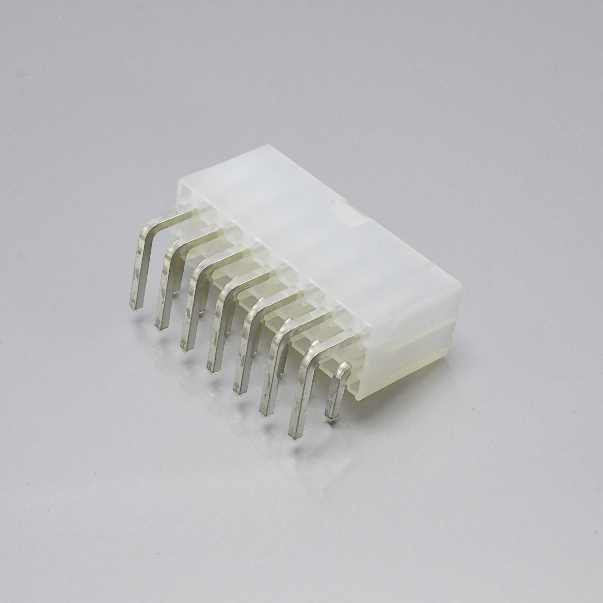
KONNRA KR4200 series dual row right angle wafer, 4.20mm board header
Why the 9A tier changes the answer
The original does not publish one current figure either — it publishes fifty-six, organised as two base metals × seven gauges × four circuit bands: brass and phosphor bronze, AWG #16 through #28, and circuit bands of 2–3, 4–6, 7–10 and 12–24.
| AWG | Brass: 2&3 ckt / 4–6 / 7–10 / 12–24 | Phosphor Bronze: 2&3 ckt / 4–6 / 7–10 / 12–24 |
|---|---|---|
| #16 | 9 / 8 / 7 / 6 | 8 / 7 / 6 / 5 |
| #18 | 9 / 8 / 7 / 6 | 8 / 7 / 6 / 5 |
| #20 | 7 / 6 / 5 / 5 | 6 / 5 / 4 / 4 |
| #22 | 5 / 4 / 4 / 4 | 4 / 3 / 3 / 3 |
| #24 | 4 / 3 / 3 / 3 | 3 / 2 / 2 / 2 |
| #26 | 3 / 2 / 2 / 2 | 2 / 1 / 1 / 1 |
| #28 | 2 / 1 / 1 / 1 | 1 / 1 / 1 / 1 |
The maximum in that table is 9A, at AWG #16 or #18 in a two- or three-circuit brass connector. Phosphor bronze tops out one amp lower at the same gauges, at 8A, so the original's headline capability is a 9A capability in a specific metal, at a specific gauge, in a specific circuit band.
Our 9A tier matches that maximum exactly: PS-KR4200-02 and PS-KR4200-04 publish 9A (16AWG), the same nominal current at the same nominal conductor as the original's ceiling, and its insulation ceiling of 3.10mm is the same figure Molex publishes as its 18 to 24 AWG maximum. That is the single strongest published correspondence between the two families on the current row, and it is only visible in the second document of each interface.
The honest half. At 20 AWG the original publishes 7A for brass and 6A for phosphor bronze in a two- or three-circuit connector, while our 5A tier publishes 5A. We are 2A below the original's brass figure and 1A below its phosphor bronze figure, and our own 9A tier does not reach 20 AWG in a way that closes the gap — the tier's window is 16# to 20#, but the 9A figure is a tier rating rather than a per-gauge table, so it cannot be read as a derating curve. Where we publish one number and the original publishes a grid, the honest comparison is at the grid's cell, not at the tier's label.
The reason this is a matter of documentation rather than of product is our own website. The terminal component page for the wire-to-board female terminal publishes Current (Max) 9A with Wire/Cable Size (AWG) 18#-22# and Insulation Diameter 2.50mm (MAX). Neither window appears in any of the four specifications, so the website publishes a third combination that exists only there, while a media asset in our own library is titled "KR4200 4.2mm Pitch 5A current single or dual row connector". A buyer can find 5A or 9A, and one of three wire windows, depending on which page they open — fixed by naming the tier on the part number and in the quotation.
A 600V Rating Carrying a 1,500V Test Level
Both families publish a 600V rating. Only one of them publishes a dielectric test level that its own rating implies. A dielectric withstanding voltage test is not a second rating, but it is not decorative either: it establishes that the insulation system survives a fault-level overvoltage for a defined period without breaking down. Molex publishes dielectric withstanding voltage 2,200 VAC for 1 minute between adjacent terminals and to ground, with the requirement "No breakdown. Current leakage < 5 mA". At the family's own 600V rating, that number is exactly two times the rated voltage plus 1,000 volts:
2 × 600 + 1000 = 2200
The 1,000V constant makes the test meaningful at low voltages, and the doubling keeps the margin proportional as the rating rises. Run the formula at 250V and it yields 1,500V; run it at 600V and it yields 2,200V. Those two results are 700V apart, and it is worth a section because our 1,500V test level appears at both ratings.
All four KR4200 specifications publish 1500V AC for one minute between adjacent terminals or ground, per EIA-364-20A, with no breakdown and no flashover. It is not a transcription error but a house figure, and the evidence is that the same 1,500V value appears in our 250V-rated 3.00mm, 3.96mm wire-to-board and 3.96mm board-in specifications as well. In the preceding comparison in this series, on 3.00mm, our 1,500V happened to equal the formula evaluated at our own 250V rating; here our rating is 600V and 1,500V is not what the formula yields at 600V, so the two documents are not consistent.
What this does and does not mean has to be stated carefully. It does not mean the connector fails a 2,200V test — no such result is published on either side, and the 600V rating is published in all four specifications and on the terminal page. It does mean that a qualification programme taking the original's dielectric row as its acceptance criterion will find our published value 700V short, and that this is a document request rather than a substitution decision. And one Molex figure must sit beside the 2,200V one: the original's older, variant-specific flange document publishes a dielectric strength of 1,500V AC(rms) for one minute on a document that also states a 600V rated voltage, so the original's own document set contains a 1,500V level at a 600V rating and a 2,200V level at a 600V rating, and this article prints both rather than choosing.
Temperature: the Original Splits by Base Metal, We Do Not
Molex publishes its operating and nonoperating temperature ranges split by the contact's base metal, in the same document whose current table is also split by base metal:
| Terminal base metal | Molex operating | Molex nonoperating |
|---|---|---|
| Brass | −40°C to +80°C | −40°C to +80°C |
| Phosphor bronze | −40°C to +105°C | −40°C to +105°C |
The footnote attaches a condition to both rows: "Including 30°C terminal temperature at rated current" — the same 30°C rise figure the current table is built on, so the temperature rows and the current rows are one statement rather than two.
KONNRA publishes one figure. All four KR4200 specifications publish an ambient temperature range of −40 to +105°C, and the component page for the wire-to-board female terminal publishes Operating Temperature Range −40°C to 105°C. The problem is not the figure. The problem is the material it is claimed for. Our specifications' materials section reads "Terminal: Phosphor Bronze/Brass Tin Plated Over Nickel" and the wafer entry reads Contact: Brass Tin Plated Over Nickel — it does not choose a metal; it lists both — while our cross-reference page describes every terminal as brass: T4200FBT0102A and T4200FBT0104B on the female side, T4200MBT0102A and T4200MBT0101A on the male side, each row naming brass and distinguishing stamp-then-tin-plate from pre-plated, that is tin-plate-then-stamp. So the cross-list chooses brass, four times out of four, where the specification leaves the choice open.
The temperature row therefore has two possible readings, and both must be printed: if the terminal is brass, our published +105°C exceeds the original's own ceiling for a brass contact by 25°C; if it is phosphor bronze, our published +105°C matches the original's phosphor bronze figure exactly. Only one of those readings is safe, and which one applies depends on a field in our own document that is not filled in.
There is a counter-intuitive half to this that the original's own table publishes. At AWG #16 and #18, in a two- or three-circuit connector, brass is rated 9A and phosphor bronze is rated 8A — brass is the better metal for current — while the temperature rows reverse the order, because phosphor bronze is rated to +105°C and brass only to +80°C. Neither metal is simply better, so a requirement of 9A at 18 AWG in a three-circuit connector and operation above +80°C is not satisfied by one metal on the original's side either. The trade exists on both sides of the comparison, and the difference is that the original documents it and we currently leave it open.
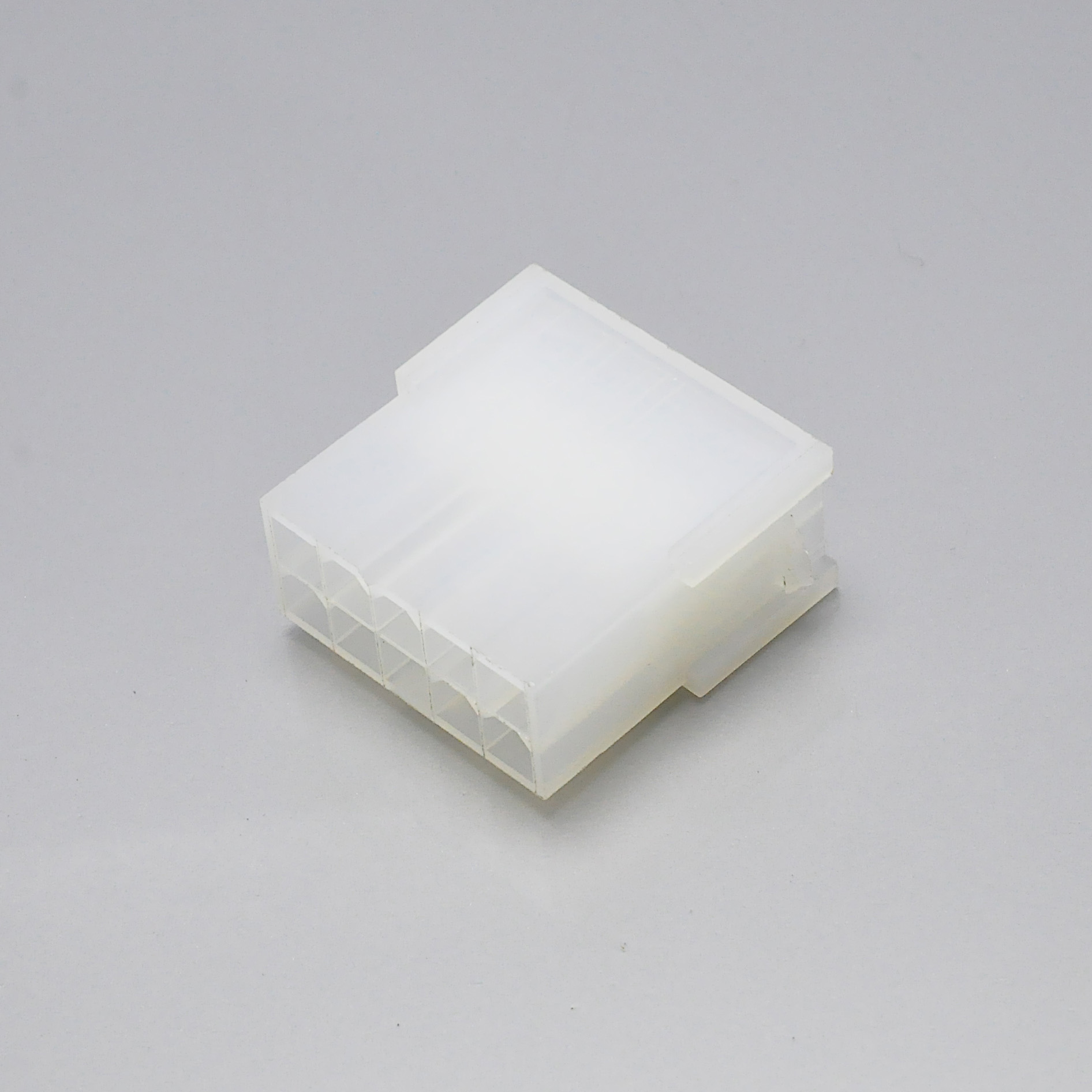
KONNRA KR4200 series dual row female housing for the Mini-Fit Jr. 4.20mm pattern
The Mechanical Layer: Three Figures Within About Two Percent
The mechanical layer is where these two families are closest, and it is a supporting section rather than the headline.
| Figure | Molex | KONNRA | Gap |
|---|---|---|---|
| Crimp terminal insertion force (into housing) | 15.0 N (3.37 lbf) maximum | 1.5 kgf (14.7 N) Max. | About 2% |
| Crimp terminal retention force (in housing) | 30 N (6.74 lbf) minimum | 3.0 kgf (29.4 N) Min. | About 2% |
| PC tail header pin retention force / pin retention | 9.81 N (2.20 lbf) minimum | 1.0 kgf (9.8 N) Min. | About 0.1% |
These are three different physical quantities, measured in three different directions, on three different parts of the system — a terminal being pushed into a housing, a terminal being pulled out of a housing, and a header pin being held in a printed circuit board. The test conditions are also close enough to compare. Molex specifies its per-circuit mate and unmate test at 25 ± 6 mm per minute, with latch disabled; our §6.1 points to §8.0 and states 25.4 ± 3 mm per minute, excluding plastic detents, per EIA-364-13D. The speeds overlap across their whole ranges — 19 to 31 mm per minute against 22.4 to 28.4 — and the exclusion clauses differ in wording and agree in intent. Two figures in the original's mechanical section have no counterpart on our side: normal force, at a minimum of 1.47 N (150 grams) for tin and 0.49 N (50 grams) for gold, where we publish no normal-force figure; and the panel, latch and PCB engagement block, listed below.
Mating force is specified per circuit rather than per connector, which is the layer a harness engineer actually uses. Molex gives 14.7 N (3.30 lbf) maximum insertion force and 0.5 N (0.11 lbf) minimum withdrawal force per circuit, measured at 25 ± 6 mm per minute with the latch disabled. Our §8.0 table is published as a whole-connector ladder for the single row family:
| Circuits (single row) | Insertion force max | Withdrawal force min, initial | Withdrawal force min, 30th cycle |
|---|---|---|---|
| 2 | 3.00 | 0.20 | 0.15 |
| 3 | 4.50 | 0.30 | 0.25 |
| 4 | 6.00 | 0.40 | 0.30 |
| 5 | 7.50 | 0.50 | 0.40 |
| 6 | 9.00 | 0.60 | 0.50 |
Units in that table are kgf as published; a dual-row table follows in the same clause. Two clean per-circuit constants fall out of it: the insertion column is a flat 1.50 kgf per circuit across all five rows, which is 14.71 N per circuit, and the initial withdrawal column is a flat 0.10 kgf per circuit, which is 0.98 N per circuit. Against the original's per-circuit figures, the insertion maxima agree to within 0.01 N per circuit, while our guaranteed withdrawal floor is about double the original's 0.5 N.
The per-circuit basis is defensible on the original's own evidence. The original's older, variant-specific flange document publishes a whole-connector table with a first-cycle, sixth-cycle and thirtieth-cycle column for 10, 12, 14, 16 and 20 circuits, in which every withdrawal minimum divides to exactly 0.49 N per circuit and every insertion maximum to 14.21 N per circuit against the current specification's 14.7 N per circuit — a difference of about three per cent between two of the original's own documents, stated here rather than smoothed. Three caveats belong with the comparison. The ladder decays, and it is supposed to: our withdrawal column carries a 30th-cycle figure lower than the first-mate figure at every circuit count. The two companies' per-circuit numbers are not the same kind of number: both publish an insertion maximum and a withdrawal minimum, which measure good news in opposite directions. And provenance: the table producing the 0.49 N and 14.21 N figures is dated 2007 and scoped to a flanged right-angle variant, not to the current specification.
The Electrical Rows That Match Exactly
The electrical layer is the most straightforward part of this comparison, and it is a supporting section here.
| Row | Molex | KONNRA | Basis on our side |
|---|---|---|---|
| Contact resistance, initial | 10 milliohms maximum, at maximum 20 mV and 100 mA with wire resistance removed | 10 milliohms Max. | Dry circuit 20mV/100mA, EIA-364-23C |
| Insulation resistance | 1000 Megohms minimum at 500 VDC | 1000 Megohms Min. | 500V DC for 1 minute, adjacent contacts, EIA-364-21B |
| Durability | 30 cycles at maximum 10 cycles per minute → 20 milliohms maximum change from initial | 30 cycles at 10 cycles/min → 20 milliohms Max. | EIA-364-09C |
| Temperature rise | +30°C maximum, by current cycling | 30 Max. | EIA-364-70B |
| Heat resistance | 96 hours at 105 ± 2°C → 20 milliohms max change | 105 ± 2°C, 96 hours | EIA-364-17B |
| Cold resistance | 96 hours at −40 ± 3°C → 20 milliohms max change | −40 ± 2°C, 96 hours | EIA-364-59 |
| Thermal shock | 5 cycles between −55 and 105°C, dwell 0.5 hours each | 5 cycles −40°C 30 min / room 5 min / +105°C 30 min / room 5 min | EIA-364-32B |
Read that table for the level rows and it is a match on every one of them. Contact resistance is 10 milliohms maximum on both sides on the same basis, our §5.1 specifying a dry circuit at 20mV and 100mA per EIA-364-23C. Insulation resistance is 1000 megohms minimum at 500V DC on both sides, our clause naming the same 500V DC for one minute between adjacent contacts. Durability is 30 cycles on both sides at the same rate of 10 cycles per minute, with the same 20 milliohms maximum change from initial. Temperature rise is 30°C and heat resistance 96 hours at 105 ± 2°C on both sides. Cold resistance is 96 hours at −40°C on both sides, with the original's tolerance at ± 3°C and ours at ± 2°C — the same nominal figure with different tolerance bands, and the tolerance is printed rather than harmonised.
One row is level in its nominal cold end and not in its test ladder. The original's thermal shock clause runs 5 cycles between −55 and 105°C with a 0.5 hour dwell at each; ours runs 5 cycles of −40°C for 30 minutes, room for 5 minutes, +105°C for 30 minutes, room for 5 minutes, per EIA-364-32B. The cycle count is the same at 5 and the hot end is the same at +105°C, but the cold end is different — −55°C on the original against −40°C on ours.
The post-humidity row is where our own numbers part company with the original. The original's general insulation-resistance requirement is 1000 megohms minimum; our §7.7 humidity test — 40 ± 2°C, 90 to 95% RH, 96 hours per EIA-364-31B — requires contact resistance within 20 milliohms, the dielectric requirement of §5.3, and insulation resistance of 100 megohms minimum. That is an order of magnitude below the 1000 megohm figure, and the identical post-humidity figure appears in our 2.5mm, 2.54mm, 3.00mm, 3.96mm and 4.20mm specifications, so it is a house clause.
Two environmental rows differ in kind rather than in value. Molex specifies random vibration per EIA 364-28 test condition VII letter D, 15 minutes in each axis; ours is a sinusoidal sweep, 1.5mm peak-to-peak, 10 to 55 to 10 Hz in one minute, 2 hours in each X.Y.Z axis, per EIA-364-28B. On shock, both sides publish 50 g: Molex specifies a half sine wave of 11 milliseconds in ±X, ±Y and ±Z axes, 18 shocks total, while ours states 490 m/s² (50g), 3 strokes in each X.Y.Z axis, per EIA-364-27B and publishes no pulse duration or waveform.
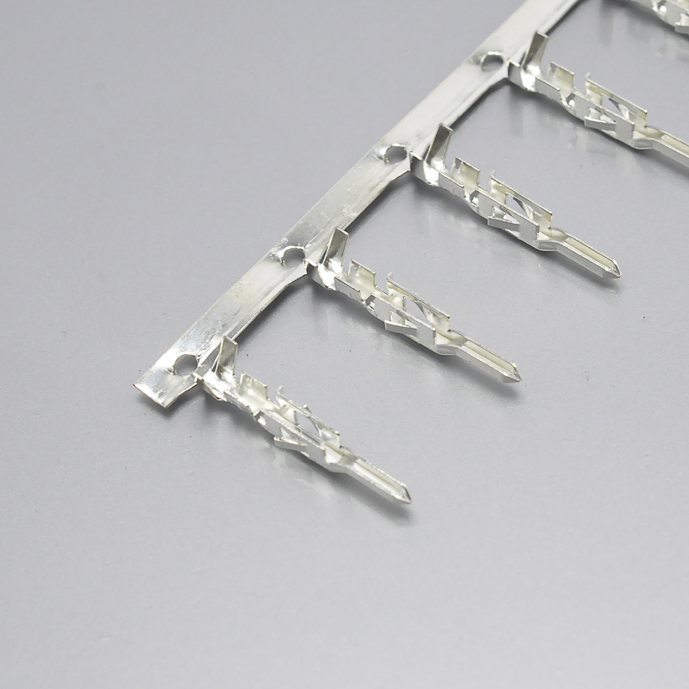
KONNRA KR4200 series female crimp terminal, brass tin plated over nickel
The Wire and Insulation Windows
This is the section to read before a quotation, because it is where three documents become four windows and one of them is 1.30mm tighter than the original's.
| Side | Wire range | Insulation window |
|---|---|---|
| Molex, 16 AWG | 16 AWG | 3.15 mm maximum |
| Molex, 18–24 AWG | 18–24 AWG | 3.10 mm maximum |
| Molex, 22–28 AWG | 22–28 AWG | 1.80 mm maximum |
| KONNRA, 5A tier | 20#–24# | 1.10–1.80 mm |
| KONNRA, 9A tier | 16#–20# | 3.10 mm Max. |
| KONNRA, terminal component page | 18#–22# | 2.50mm (MAX) |
We do not cover 26 or 28 AWG on either tier. The original's range runs to 28 AWG, with published currents down to 2A for brass and 1A for phosphor bronze at 28 AWG in a two- or three-circuit connector and an insulation window of 1.80mm for the fine-wire group, while our 5A tier starts at 20# and our 9A tier starts at 16#. A 26 or 28 AWG harness requirement is a coverage question, not a cross-reference question.
The 5A tier's insulation ceiling is 1.30mm tighter than the original's for the 18 to 24 AWG group: the original allows 3.10mm, our 5A tier allows 1.80mm, and a 20 AWG wire with 2.5mm of insulation is acceptable to the original and outside our 5A tier's ceiling. The tightest published insulation limit in this comparison is ours, on the tier most customers will be sent first. The two tiers also constrain opposite ends: our 5A window has a floor and a ceiling, the original's 18 to 24 AWG window has 3.10mm maximum only, and our 9A window is 3.10mm Max. with no minimum, which makes the higher-current tier the looser one. The terminal component page's 18# to 22# with 2.50mm belongs to neither tier.
The crimp settings follow the window. Our §6.5 publishes conductor crimp heights of 1.05 / 1.00 / 0.87 ± 0.05mm for 20 / 22 / 24 AWG, an insulation crimp width of 2.30mm maximum with insulation crimp heights of 1.65 / 1.55 / 1.45mm maximum, a stripping length of 2.6 to 3.2mm, and crimp strengths of 6.80 / 4.54 / 3.63 kgf minimum. A customer who moves to the 9A tier's 16# to 20# range is moving to a different terminal part number, and the settings for the 9A terminal are in PS-KR4200-02 rather than in the file that was sent with the quotation.
What the Original Publishes That We Do Not
Agency files with numbers. Molex publishes UL File E29179, CSA Certificate LR 19980 and IEC 61984, plus a per-series table showing UL(600V), CSA(600V) and IEC(250V); our component pages publish UL E482542 only. A current table by material, gauge and circuit count, and a temperature table by base metal. The original gives 56 cells and two temperature rows, +80°C for brass and +105°C for phosphor bronze; we give one figure per tier and one temperature for a terminal whose material section lists both metals.
Glow wire. Molex names eight series — 46992, 46993, 46994, 172646, 172447, 172448, 172648 and 45776 — and publishes the standard as EN 60695-2-11-2001 / IEC 60695-2-11-2000, with an EN 60335-1 / IEC 60335-1 750°C for 2 seconds, no flaming investigation. We publish no glow-wire data at all.
Wave solder, normal force, and panel and latch mechanics. Molex publishes 240°C maximum with pegs, 260°C maximum without pegs and with matte tin over nickel, 240°C for bright tin over nickel, 240°C for tin over copper and 220°C with pegs for the glow-wire series; normal force minima of 1.47 N (150 grams) for tin and 0.49 N (50 grams) for gold; 225 N maximum panel insertion with 157 N dual row and 133 N single row minimum panel withdrawal for 5559, 46993 and 172646, and 225 N maximum and 133 N minimum for 45776; 22.24 N (5.0 lbf) maximum thumb latch operation force and 68 N (15.3 lbf) minimum thumb latch yield strength; and PCB engagement forces of 26.7 to 66.7 N for the right angle headers and 4.4 to 44.5 N for the straight headers. We publish none of them.
Environmental programmes, solderability, packaging and harness guidance. The original publishes mixed flowing gas to EIA-364-65 Class IIa, 10 days mated, for 30µ" gold plated parts only, cyclic temperature and humidity to EIA-364-1000.01, 24 cycles from 25°C/80% RH to 65°C/50% RH, solderability at 95% minimum coverage per SMES-152, the nylon moisture warning, the test-plug recommendation (Series 44281) and a cable-tie free-length table from 12.7mm to 44.45mm. Our PS-KR4200-01 carries none of those clauses. Where the absence runs the other way, the older Molex flange document publishes a salt spray test of 48 ± 4 hours at 35 ± 2°C from a 5 ± 1% solution and an SO2 gas test of 50 ± 5 ppm for 24 hours at 40 ± 2°C, but the current Molex specification contains no salt spray clause and ours has none either, so the correct statement is the absence of a comparison.
Where Our Own Documents Disagree With Each Other
This is the longest defect list in this comparison series so far, and all of it is ours.
- The series publishes two tiers and the website matches neither: the specifications publish 5A / 20#–24# / 1.10–1.80mm and 9A / 16#–20# / 3.10mm Max., the terminal component page publishes 9A with 18#–22# and 2.50mm, and a media asset is titled "KR4200 4.2mm Pitch 5A current single or dual row connector".
- All four documents share one document-number block and one date — Edition A1 dated 2022/2/26 — and two carry the same subject line as each other.
- One KONNRA part number is mapped to two Molex references whose descriptions contradict each other:
H4200F2111602Aappears for both5559-22P(with wings, clear) and5559-22P1(without wings, clear), andH4200F2121602Afor both5559-24Pand5559-24P1. The suffix difference is exactly the wings. - One part number is mapped to both flammability grades of the same housing:
H4200M2011601Amaps to5557-02R(clear) and to5557-02R-210(white PA66 UL94-V0), where Molex distinguishes5557-NR(UL 94V-2) from5557-NR-210(UL 94V-0). - The 22-circuit row carries two position counts in the same column:
5557-22R-210maps toH4200M2110101A, described as 2X10P, while5557-22Rmaps toH4200M2111601A, described as 2X11P. - A plug housing is mapped against board headers, since the cross-list puts 5559-nnA4 references against our single-row right-angle DIP wafers where Molex's own map lists
5559as a Plug Housing and5569as the Right Angle Header. - The Standard column reads RoHS/REACH on every row, and the cross-list has no electrical column at all: no voltage, no current, no temperature, no wire range and no insulation diameter.
- The page a search finds first publishes no electrical specification whatever, stating that "Detailed dimensional and electrical datasheets are not itemized in the current catalog record."
None of those eight items is a product decision. Every one is a publication decision, closed by naming a tier on a document, choosing a metal on a drawing, or correcting a mapping row.
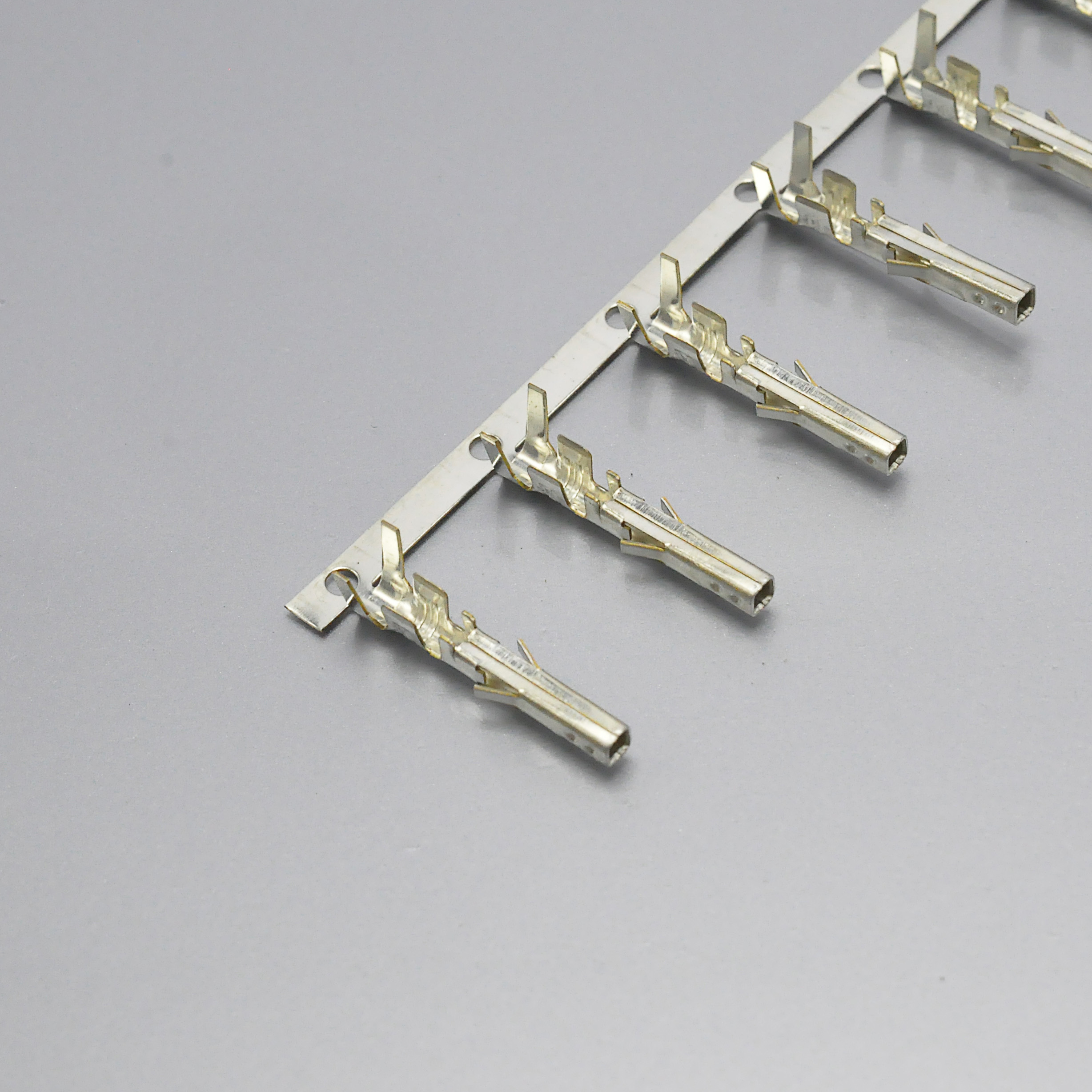
KONNRA KR4200 series male crimp terminal, brass tin plated over nickel
The Cross-Reference Map
Our cross-reference is a real HTML table of about 110 rows, with columns for Brand, Brand MPN, Konnra MPN, Compatible Series, KONNRA Product Series, Pitch, Spec and Standard. It answers "which of ours do I ask for" and it does not answer "will it work". It maps the 5557 receptacle housings, the 5559 plug housings, the 5556 and 5558 terminals, the 5569-02A2 to 24A2 right angle headers and the 5566-02A to 24A and 5566-02A2 to 24A2 vertical headers. All rows are marked 4.2mm and "wire to board", and packaging is described as bagged or boxed. The four terminal rows are the only rows carrying a material statement:
| Molex reference | KONNRA reference | Description given |
|---|---|---|
5556T2 |
T4200FBT0102A |
Female terminal, brass, stamp then tin plate, low foot |
5556T3 |
T4200FBT0104B |
Brass, tin plate then stamp, high foot |
5558T2 |
T4200MBT0102A |
Male terminal, brass, stamp then tin plate, low foot |
5558T3 |
T4200MBT0101A |
Brass, tin plate then stamp, high foot |
So the cross-list distinguishes stamp-then-plate from pre-plated, and it names brass in all four rows — the origin of the material contradiction in this comparison. Our part list is published in the specifications: the housing is H4200M***1601A, and the wafers are C4200RD1**16T0101PC, C4200RD1**16T0102PC, C4200VD1**16T0101PC, C4200RD2**16T0101PC, C4200RD2**16T0102PC, C4200VD2**16T010*PC, C4200VD2**16T0103*B and C4200VD2**16T0104*B. There are roughly 22 KR4200 component pages on our site.
Applications, Sourcing and the Questions To Ask
The 4.2mm pattern is an internal power-and-signal crimp interface rather than a user-facing port: a 4.20mm pitch with currents from 1A to 9A, a 30 cycle durability rating at 10 cycles per minute, a crimp set on an applicator, and a panel-mount housing range with a latch. The board side is chosen first — straight header (5566, 172447, 172647) or right angle header (5569, 172448, 172648) where the harness plugs onto a board, and crimped terminals at both ends where two harness halves mate in mid-air. The original hands the thermal evaluation back to the application, twice: "PCB trace design may greatly affect temperature rise results in Wire-to-Board Applications" and "Current rating is application dependent... Each application should be evaluated by the end user". Where the original says evaluate it, our tier figure is a single number with no test basis attached.
KONNRA supplies the KR4200 as individual components, crimped housing assemblies or complete wire harnesses, with customisation for application-specific requirements. Complete connector set samples are available within 45 days. Connector production lead time is typically 2 to 4 weeks, and wiring harness lead time is typically 3 to 4 weeks. For procurement, four things need answering from a document rather than a negotiation: the tier and the terminal part number (PS-KR4200-01 / -03 or PS-KR4200-02 / -04); the base metal in writing, because the specifications say Phosphor Bronze/Brass while the cross-list says brass four times; the approval file, with our UL E482542 against UL E29179 / CSA LR 19980 / IEC 61984; and the timing, with packaging described as bagged or boxed. Put the tier, the terminal part number, the conductor, the insulation diameter and the metal in the enquiry.
The five questions I would ask us, in this order: which tier is on the quotation and which terminal goes with it; which base metal the terminal is, in writing, and what temperature ceiling that metal carries; what the dielectric withstanding voltage is as tested on this part number, and whether 1,500V is a family convention or derived from the 600V rating; which wire window applies against the specific conductor on the drawing; and what the current is at our gauge, with the test basis, and what the dual-row table says.
Engineer's pre-release checklist: put the tier and the terminal part number on the drawing first, because everything else follows from the terminal; get the terminal material in writing, since if the answer is brass our +105°C exceeds the original's brass ceiling by 25°C; get the dielectric row tested on the part number; check the insulation diameter at both ends, because a 20 AWG wire with 2.5mm of insulation passes the original and fails the 5A tier's ceiling; confirm wire range coverage, since we publish no 26 or 28 AWG tier; read the current at the conductor rather than at the tier label, against the original's 9A / 8A at 16 to 18 AWG in 2 to 3 circuits, 7A / 6A at 20 AWG and 5A / 4A at 22 AWG; confirm the crimp settings and the stripper, because a second tier means a second setting; confirm life and forces, at 30 cycles, 14.71 N per circuit against 14.7 N, and 0.98 N per circuit against 0.5 N; and confirm approvals, glow wire and post-humidity, where our 100 megohms minimum sits against the original's general 1000 megohms minimum.
Frequently Asked Questions
What is a Molex Mini-Fit Jr. connector?
A 4.20mm (.165 inch) pitch crimp family for wire-to-board and wire-to-wire use, terminated with 16 to 28 AWG stranded copper wire and available with tin or 30µ" gold plating, with the wire half as female terminal 5556 in housing 5557 or male terminal 5558 in housing 5559, and the board half as the vertical header 5566 or the right angle header 5569. Molex rates it 600V AC/DC and publishes a 56-cell current table whose highest figure is 9A.
What is the KONNRA KR4200?
Our 4.20mm pitch crimp series for the same two interfaces, documented in four specifications, all Edition A1 dated 2022/2/26, two per interface, in a 5A (20AWG) tier and a 9A (16AWG) tier, with 600V AC/DC and −40 to +105°C in all four.
Is the KR4200 a drop-in replacement for the Molex Mini-Fit Jr.?
On the electrical level rows and the mechanical forces, it lines up well: contact resistance 10 milliohms, insulation resistance 1000 megohms at 500V DC, durability 30 cycles with 20 milliohms maximum change, temperature rise 30°C, and a per-circuit insertion maximum within 0.01 N. Three rows do not line up: the dielectric test level, at 1,500V against 2,200V; the temperature ceiling, which is one figure for a terminal whose metal is left open; and 20 AWG, where our 5A sits below the original's 7A brass / 6A phosphor bronze.
Is the KR4200 a 5A connector or a 9A connector?
Both, in different documents. PS-KR4200-01 and -03 publish 5A (20AWG) over 20# to 24# with insulation 1.10 to 1.80mm; PS-KR4200-02 and -04 publish 9A (16AWG) over 16# to 20# with insulation 3.10mm Max. The 9A tier is the one that matches the original's maximum, so name the tier on the purchase order.
Why is the 9A tier the important one?
Because the original's own maximum is 9A, at AWG #16 or #18 in a two- or three-circuit brass connector, and our 9A tier publishes the same nominal figure at the same nominal conductor, with a 3.10mm insulation ceiling — the same figure Molex publishes for its 18 to 24 AWG window.
What is MX4.2?
The catalogue shorthand used in Asia for the 4.20mm Molex Mini-Fit Jr. pattern — "MX" for Mini-Fit and 4.2 for the 4.20mm pitch. A requirement that arrives as "MX4.2" fixes the pitch and says nothing about the tier, the metal, the wire window or the circuit count.
What current does the original carry at 20 AWG, and what do we carry?
Molex publishes 7A for brass and 6A for phosphor bronze at 20 AWG in a two- or three-circuit connector; our 5A tier publishes 5A at 20 AWG, and our 9A tier states its rating as the tier's 9A (16AWG) figure rather than as a per-gauge table. At the gauge where both sides publish a figure for the same conductor, our number is 1A to 2A lower.
What is the voltage rating, and are the two companies level?
Both publish 600V AC/DC. The original publishes voltage per agency — UL(600V), CSA(600V) and IEC(250V) — while our four specifications publish one figure, 600V AC/DC. We are level with the original's UL and CSA columns and not level with its IEC column.
Why is the dielectric test level different from the original's?
Molex publishes 2,200 VAC for one minute with leakage under 5 mA — exactly two times its 600V rating plus 1,000 volts — while our four specifications publish 1500V AC for one minute, 700V below what the formula yields. It is a house figure: the same 1,500V appears in our 250V-rated 3.00mm and 3.96mm specifications.
What is the operating temperature range?
We publish −40 to +105°C in all four specifications. The original publishes two ranges, split by base metal: brass terminals −40 to +80°C, phosphor bronze terminals −40 to +105°C, with the footnote "Including 30°C terminal temperature at rated current". If the terminal is brass our +105°C exceeds the original's brass ceiling by 25°C; if it is phosphor bronze the figures match.
What wire gauges and insulation diameters are supported?
On the 5A tier, 20# to 24# with insulation 1.10 to 1.80mm; on the 9A tier, 16# to 20# with insulation 3.10mm Max.; the terminal page adds 18# to 22# with 2.50mm. The original publishes 16 to 28 AWG across three windows: 3.15mm at 16 AWG, 3.10mm at 18 to 24 AWG and 1.80mm at 22 to 28 AWG, and no 26 or 28 AWG exists on either of our tiers.
What are the mating forces per circuit?
The original specifies 14.7 N maximum insertion and 0.5 N minimum withdrawal per circuit, with the latch disabled. Our §8.0 single-row table divides to 14.71 N per circuit maximum insertion and 0.98 N per circuit minimum withdrawal at first mate, so the insertion maxima agree to within 0.01 N and our withdrawal floor is about double the original's.
What are the contact resistance and insulation resistance?
Both exact matches, on the same dry-circuit basis at 20mV and 100mA per EIA-364-23C, and at 1000 megohms minimum at 500V DC. The departure is post-humidity: our §7.7 requires 100 megohms minimum, against the original's general 1000 megohms.
How many mating cycles does it survive?
30 cycles on both sides, at a maximum rate of 10 cycles per minute, with a maximum change in contact resistance of 20 milliohms from initial. The original's rating is plating-specific, based on 30µ" gold or 50µ" tin at the contact interface.
What certifications does each carry?
Our component pages publish UL E482542; the original publishes UL File E29179, CSA Certificate LR 19980 and IEC 61984, plus the per-series UL(600V) / CSA(600V) / IEC(250V) table and eight glow-capable series tested to EN 60695-2-11 / IEC 60695-2-11. We publish no glow-wire data.
Does the KR4200 come in wire-to-wire as well as wire-to-board?
Yes, documented separately for each. PS-KR4200-01 and -02 cover wire-to-board; PS-KR4200-03 and -04 cover wire-to-wire, adding a male terminal — T4200MBT0102A on the 5A tier and T4200MBT0101A on the 9A tier. All four publish the same 600V AC/DC and the same −40 to +105°C.
How long do samples and production take?
Complete connector set samples within 45 days. Connector production lead time is typically 2 to 4 weeks, and wiring harness lead time is typically 3 to 4 weeks. Include the tier, the terminal part number, the conductor, the insulation diameter and the terminal base metal in the enquiry.
Start Your Cross-Reference Check
KONNRA supplies the KR4200 series as individual components, crimped housing assemblies or complete wire harnesses, with customisation for application-specific requirements.
- Request a quote or a sample — KR4200 pricing, MOQ and configuration for your circuit count and wire; complete connector set samples within 45 days
- Name the tier on the request — the 5A (20AWG) tier of PS-KR4200-01 / -03 or the 9A (16AWG) tier of PS-KR4200-02 / -04, with the terminal part number that goes with it
- Request the terminal base metal in writing — brass or phosphor bronze, reconciled against the original's +80°C and +105°C ceilings
- Request the dielectric test level for your part number — whether our 1,500V AC is a family convention or derived from the 600V rating
- Request the wire and insulation windows reconciled, with the current derating basis and the dual-row table
- Request a material declaration, the post-humidity insulation resistance and the agency statement — with our 100 megohms minimum against 1000 megohms minimum, and our UL E482542 against UL E29179 / CSA LR 19980 / IEC 61984
- Submit a drawing for review — we will flag any specification mismatch before you commit tooling or a board respin
Contact KONNRA Electronics: phone (86)-769-85449875 · email info@konnra.com · No.6 Nanchang South Road, Chijiao, Wangniudun, Dongguan, Guangdong, China · Contact us
👉 KR4200 cross-reference for the Molex Mini-Fit Jr. 5556/5557/5558/5559 series · KR4200 female terminal, wire-to-board · Wire-to-board connector range · Wire-to-wire connector range
Sources and method. Every figure here is taken from a manufacturer document, and where two documents disagree both figures are printed rather than averaged or reconciled. Two Molex documents were used: PS-5556-001 REV E8, dated 2016/05/09, 12 sheets, titled PRODUCT SPECIFICATION FOR MINI-FIT JR. CONNECTOR SYSTEM, which supplied the scope statement, both series maps, the agency columns, the 600V AC(RMS) or 600V DC rating based on UL 1977, the three applicable-wire windows, the 56-cell maximum-current table, the temperature ranges split by base metal, the wave-solder temperatures, the glow-wire series list, the electrical, mechanical and environmental clauses, the packaging guidance, the Series 44281 test-plug recommendation and the cable-tie free-length table; and PS-5557-001 REV B, dated 2007/09/25, 9 sheets, titled NEW MINI FIT CONNECTOR WITH FLANGE RIGHT ANGLE, which supplied the variant part numbers 5556APBT(L), 5557-NR, 5557-NR-210, 5569-NB1 and 5569-NB1-210, the 1.3mm to 3.1mm insulation window, the 1500V AC(rms) for one minute dielectric strength, the crimp pull-out forces, the whole-connector insertion and withdrawal table and the salt spray and SO2 clauses. Where those two documents differ — notably 2,200 VAC against 1,500V — both are printed.
Four KONNRA documents were used: PS-KR4200-01, -02, -03 and -04, all Edition A1 and all dated 2022/2/26. The cross-reference page (page 16274) titled "KR4200 equivalent to molex mini-fit jr 5556/5557/5558/5559 series" supplied the mapping rows, the brass designations and the RoHS/REACH Standard column. The component page kr4200-female-terminal-wtb (id 2822) supplied the 9A, 18# to 22#, 2.50mm combination and UL E482542. An existing site article, post 18677, supplied its statement that dimensional and electrical datasheets are not itemized in the catalog record, alongside a media asset titled "KR4200 4.2mm Pitch 5A current single or dual row connector". Site assets referenced by those pages include KR4200-Series-Drawing_WTB.pdf, KR4200-Series-Drawing_WTW.pdf, KR4200-Series-Female-higt-foot-terminal_5.pdf and roughly 22 KR4200 component pages. No dual-row insertion and withdrawal values, no normal-force, glow-wire, wave-solder, solderability, mixed-flowing-gas or cyclic-humidity data and no third-party or NRTL report for the KR4200 were available, so those rows are recorded as gaps rather than as comparisons; there is no salt spray clause in either the current Molex specification or PS-KR4200-01, and no KONNRA housing or wafer dimensions, so no footprint comparison is made.
https://konnra.com/molex-5557-cross-reference-kr4200-mx4-2-connector-guide/
Dongguan Konnra Electronics Co., Ltd
