What is the Molex PanelMate connector, and is it a panel-mount part?
No — and the name causes an expensive mistake often enough that it is worth settling before anything else.
Molex's own part data for the 51146 receptacle housing records Panel Mount: No. "PanelMate" refers to flat panel displays, not to mounting through a chassis panel. Molex's series description says the connectors were designed for "Flat Panel Display Panels that require thin, low profile connectors" — and its product specification opens with the scope line "1.25mm Pitch Wire to Board SMT Connector", which tells you the two things that matter: the board side is surface mount, and the connector mounts to the PCB, not to the enclosure.
If your requirement is a bulkhead or chassis-panel feed-through, neither the original nor any cross-reference of it is the right part — and the requirement that decides which family you need is the panel, not the pitch.
I work on connector and harness programmes at KONNRA, which builds a documented cross-reference to this system (the KR1253). Here is what actually matters about the part.
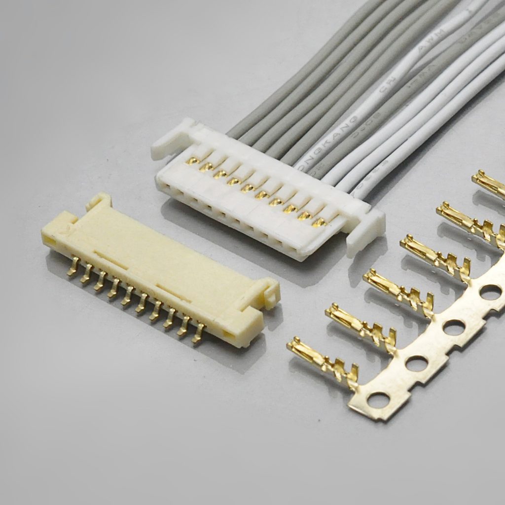
What the Molex PanelMate is
Molex describes it as "the lowest profile of any fully-shrouded wire-to-board system from Molex", and it is sold at three heights depending on which board-side header you select.
- Pitch: 1.25mm, single row, wire-to-board
- Wire side: 51146 receptacle housing ("Ultra Low Profile")
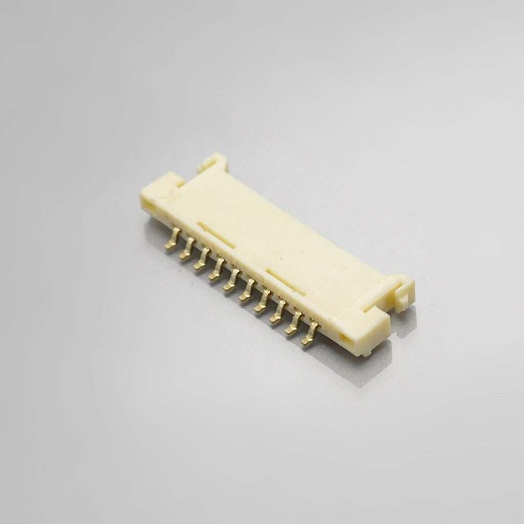
- Board side: 53779 · 53780 · 55063 plug assemblies (SMT, right-angle, shrouded)
- Crimp terminals: 50641 for AWG #28–30 · 50753 for AWG #30–32
- Voltage: 125V AC (RMS)/DC
- Current: 1.0A maximum per contact, with the note that the sum across circuits must not exceed the maximum allowable
- Wire: AWG #28, #30, #32
- Insulation O.D.: φ0.9mm max at #28 and #30, but only φ0.55mm max at #32 — a gauge-specific window
- Operating temperature: −40°C to +85°C, including terminal temperature rise
- Durability: 30 mating cycles in Molex's product specification; the 53780 part data says 50
- Profile height: 1.03mm (55063) · 1.3mm (53779) · 1.85mm (53780) — molex.com describes the 53780 as "1.90mm Height"
- Contact: phosphor bronze
- Plating: gold on the mating interface, tin on the termination — 0.200µm min mating and 3.000µm min termination on the 53780 header
- Standards: UL E29179, CSA LR19980
- KONNRA equivalent: KR1253
The other trap: at 1.25mm, Molex sells two families that look electrically identical
This is where most cross-references go wrong, because PanelMate and PicoBlade agree on almost every headline number:
- Pitch: 1.25mm — the same
- Voltage: 125V — the same
- Current: 1.0A per contact — the same
- KONNRA equivalents: KR1253 for PanelMate, KR1250 / KR1251 for PicoBlade
And they are different connector systems that do not mate. The board-side footprints differ, the mating interfaces differ, and the ultra-low profile that PanelMate exists to deliver is not reproduced by PicoBlade.
So what actually separates them? Not the electrical rating — the profile height and the configuration. PanelMate is wire-to-board only, built to sit as flat as possible against a display board, and sold by height. PicoBlade covers wire-to-board and wire-to-wire, uses a two-point contact design, and runs 2 to 15 circuits as the mainstream 1.25mm workhorse. If your design was released against a PanelMate part number, a PicoBlade cross-reference is not equivalent — even though a datasheet comparison will show matching pitch, voltage and current.
And the original is being withdrawn on a published schedule
This is now the strongest documented reason to open the enquiry at all:
- 51146 housing — recorded as Not Recommended For New Design, with 5055650501 given as a replacement part number
- 53780 header — recorded as Obsolete, under product change notification 516676, issued 2025-03-10 with an implementation date of 2026-05-31
- The 506418041 terminal — also Not Recommended For New Design, with 5054311100 as the replacement
That implementation date has now passed. A connector family being withdrawn on a published schedule is a programme risk regardless of who supplies the replacement, so ask any second source for a product lifecycle statement and a change notification process, not just a price.
Why "it mounts to the board" changes the reliability question
If the connector is not fastened to the enclosure, then the retention load lands on the solder interface. The 53780 header has solder tabs — "fitting nails" in Molex's own wording — and a solder-conducting fillet tail design, and that is the primary retention feature of the series. Molex's note list is explicit about the consequence: all terminal tails and fitting nails must be soldered, and leaving any soldering area open risks terminal drop-out, pin-to-pin short circuits, terminal buckling, or the connector coming off the PCB.
That warning is not boilerplate on this family. The whole product exists because a 1.25mm connector on a thin display board has almost no room for a retention feature, so the retention has to come from the solder joint.
Cross-referencing to the KONNRA KR1253 — what agrees, and what to verify
Where the documents agree is worth stating, and on this family the agreement is broad: the 1.25mm pitch, the single-row, wire-to-board configuration, the 125V rating, 1.0A per contact, the AWG #28–32 wire range, the 20mΩ maximum initial contact resistance, the 100MΩ minimum insulation resistance, the 30-cycle durability figure, the 30°C maximum temperature rise, the phosphor bronze contact material, the friction-lock retention concept, and the vibration and shock test conditions — both sides write them to 1.5mm P-P, 10–55–10 Hz, and 490 m/s² (50G) shock.
Where they differ, in the order the differences bite:
- Operating temperature — the largest single difference. Molex rates the family to +85°C; KONNRA documents −40°C to +105°C. That is 20°C at the top end, and the heat-resistance tests differ too: Molex runs 85±2°C for 96 hours, KONNRA 105±2°C for 96 hours. If your thermal analysis assumes 105°C because the replacement says so, substantiate it against your own testing rather than reading it off a datasheet.
- The dielectric withstanding voltage — and KONNRA's own documents disagree with each other. Molex specifies 250V AC (RMS) for 1 minute. KONNRA's product page and housing drawing also say 250V AC/minute — so the product page agrees with the original. But KONNRA's specification PDF §5.3 and the terminal drawing state 500V AC for 1 minute. Do not quote 500V without resolving which document governs. The rated voltage is 125V on both sides either way.
- Contact resistance — the KONNRA product page is an outlier against its own specification. The product page says 30mΩ Max; KONNRA's specification §5.1 and all three of its drawings say 20mΩ Max, as do its component pages — and Molex says 20mΩ max. The figure to work from is 20mΩ.
- The insulation window does not fully overlap at AWG #32. Molex allows φ0.9mm at #28 and #30 but only φ0.55mm at #32. KONNRA documents a single window of 0.6 to 0.9mm with no gauge split. A wire that satisfies KONNRA's 0.6mm lower bound is outside Molex's φ0.55mm maximum for #32 — so a #32 design cannot be validated against both documents at once.
- Plating thickness is specified by Molex and not by KONNRA. Molex publishes micron figures (0.200µm / 0.203µm min mating, 3.000µm min termination). KONNRA publishes "Tin or Gold flash over Nickel" with no thickness. The word "flash" is not a thickness specification on either side.
- Durability is 30 cycles on one Molex document and 50 on another. The product specification says 30, the 53780 part data says 50. KONNRA says 30 — so 30 is the figure both sides substantiate.
- The terminal split is not replicated. Molex splits the crimp terminal by wire range across 50641 (#28–30) and 50753 (#30–32), overlapping at AWG #30. KONNRA documents one terminal pair —
T12530PG0201A(gold) andT12530PT0101A(tin) — across AWG #28–32. A design that depends on the specific crimp barrel geometry of one Molex series should ask for it directly. - Crimp and retention forces are claimed higher by KONNRA, on its own test method. Molex gives crimp pull-out minimums of 9.8N / 4.9N / 2.9N at #28 / #30 / #32; KONNRA lists 1.36 / 0.9 / 0.7 kgf for the same gauges, which is higher. Same for terminal retention (Molex 4.9N min, KONNRA 0.7kgf = 6.86N min). Not automatically a problem — but a different test claim on a different crimp barrel.
- Circuit counts run wider on the KONNRA side, and KONNRA's own drawings disagree. Molex's 53780 part list enumerates 2, 3, 4, 5, 6, 7, 8, 9, 10, 14, 15 and 20 circuits. The KONNRA housing drawing says 2~15, 20, 30; the product page says 2–30; the wafer drawing says "2~20,30", which omits 15. Treat 30 as beyond the published Molex range and confirm both the count and which drawing governs.
- One published KONNRA row looks like a typo — do not quote it. Its insertion/withdrawal table lines up exactly with Molex at the low end (2 circuits = 0.44 kgf max insertion and 0.04 kgf min withdrawal, i.e. 0.22 and 0.02 kgf per circuit). But the 15-position row shows withdrawal of 2.30 kgf, against a pattern predicting 0.30 kgf. Treat that row as unverified.
- Also documented by Molex and not by KONNRA: wire construction (Molex: tin-plated copper stranded in principle, other constructions require consultation), and SO₂ / NH₃ gas exposure tests. If your qualification includes either, they are open items.
Design cautions worth carrying into your review
Molex publishes thirty-seven numbered notes in PS-51146-010. They are the failure modes the product is known to have, and the most useful part of the document. Five that matter most here:
- Do not mate or unmate under load. Molex states the product is not designed for mating or unmating under an active circuit, and that doing so "may cause a spark and product defect".
- No continuous pulling or stress force when mated — it damages the contact area, the crimp and the terminal lock. Leave slack so no tension reaches the connector, and never carry the board by the harness.
- Solder every terminal tail and every fitting nail. Leaving any pad open risks terminal drop-out, pin-to-pin shorts, terminal buckling, or the connector coming off the board.
- Use a new housing after extracting a terminal. Extracting with a jig deforms the housing lance and, in Molex's words, "reduce the terminal retention force enormously" after re-insertion.
- Coplanarity is a pre-mount specification. Molex requires PCB warpage of 0.02mm maximum across the connector, and states coplanarity is assured only before mounting — there is no guarantee after mounting or reflow. Air reflow is assumed; N₂ reflow requires separate evaluation because solder wicking can occur.
Also worth putting on the drawing: the KONNRA reflow peak is 255±5°C against Molex's 250 +5/−0°C, with matching preheat (90–120s at 150–200°C) and time-above-liquidus (20–40s at 230°C minimum) windows.
What to send for a cross-reference check
- The original part number, if you have it — a housing such as
51146-**00, a terminal such as50641-8***or50753-8***, or a plug assembly such as53780-**19 - Circuit count — Molex's 53780 part list runs to 20; KONNRA documents up to 30, which needs raising explicitly
- The header height you need — Molex offers 1.03mm, 1.3mm and 1.85mm; KONNRA documents a 1.90mm minimum height, so height is the first thing to reconcile
- Wire gauge and insulation outside diameter — and specifically whether you are on AWG #32, where the two windows do not fully overlap
- Plating finish required — gold flash, or a specified thickness in microns
- Which terminal series your approved part number names — 50641 (#28–30) or 50753 (#30–32)
- Your required operating temperature, since this is the largest documented difference (+85°C versus +105°C)
- Load current and circuit count, so the per-circuit rating and the sum-of-current note are settled rather than assumed
- Whether the connector must fasten to an enclosure panel — if it must, neither part number is right
- Application and annual volume, plus a drawing or photo if the part number is unreadable
With those, four things get confirmed against Molex's own documentation: the terminal that matches your wire gauge and insulation diameter, the gold thickness you need, the header height and mounting type, and whether your design needs something beyond the published range.
One quick check if you are holding the part. Measure the pitch — 1.25mm points at PanelMate, PicoBlade, Hirose DF13/DF14 or JST GH; 1.20mm at Pico-EZmate; 1.00mm at Pico-Clasp or JST SH. Then measure the mated height: PanelMate is sold by height (1.03 / 1.3 / 1.85mm), which is what identifies the variant. Check the mounting type — the board side is surface mount, so a through-hole header at this pitch is a different family. Look for the solder tabs / fitting nails. And read the part number: 51146 housing, 53779 / 53780 / 55063 plug assemblies, 50641 / 50753 terminals.
Full technical write-up: Molex PanelMate Connector Complete Guide
Disclosure: I work with KONNRA, which manufactures the KR1253 cross-reference. The Molex PanelMate figures above are taken from Molex's published product specification PS-51146-010 and molex.com part data for the 51146 housing, 53780 header and 506418041 terminal; the KONNRA figures are from KONNRA's published KR1253 documentation and specification PS-KR1253-01. Where the two sources disagree — or where one source contradicts itself — I have flagged the difference rather than averaged it, and I have marked the KONNRA 15-position withdrawal-force row as unverified rather than quoting it.
https://konnra.com/molex-panelmate-mx1-25-connector-complete-guide/
Dongguan Konnra Electronics Co., Ltd
