Electromagnetic Flow Meters for District Heating Water Guide
Electromagnetic Flow Meters for District Heating Water Systems
District heating networks circulate large volumes of conductive hot water between energy centers, substations, and end users. Accurate flow measurement at each transfer point is essential for load balancing, leak detection, and billing verification. This guide explains how electromagnetic flow meters function in district heating water applications, what conditions must be verified before selection, and how engineering teams — including EPC contractors, thermal energy operators, and system integrators — can specify equipment that performs reliably over the service life of a heating pipeline.
Why Electromagnetic Flow Measurement Suits Conductive Heating Water
Electromagnetic flow meters operate by inducing an electromotive force proportional to the velocity of a conductive fluid moving through a magnetic field. Because treated and untreated district heating water almost always carries dissolved minerals and ions, it typically meets the minimum conductivity threshold required for electromagnetic sensing.
Key reasons this measurement principle fits district heating water:
- No moving parts in the flow path — reduces mechanical wear from continuous high-temperature circulation.
- Bidirectional measurement capability — supports systems where flow direction may reverse during load balancing or return-line monitoring.
- Stable signal generation — square wave pulse excitation combined with VFC (voltage-to-frequency conversion) signal processing and high-input-impedance amplification helps maintain zero-point stability even as water temperature (and therefore conductivity) shifts seasonally.
- Multiple output options — 4-20mA, pulse, and frequency outputs allow integration with PLC, DCS, or SCADA systems commonly used by heating network operators.
Before selecting an electromagnetic flow meter for a heating water application, engineers should verify:
- Minimum and maximum operating conductivity of the circulating water across heating and non-heating seasons.
- Whether the water is treated, softened, or contains variable mineral content that could affect signal consistency.
- Operating temperature and pressure envelope of the specific pipeline segment (supply line vs. return line).
- Actual flow velocity range under normal and peak-load conditions.
Understanding District Heating Water Measurement Conditions
Water Conductivity
District heating water conductivity can vary between heating seasons due to water treatment cycles, make-up water addition, and corrosion inhibitor dosing. Electromagnetic flow meters rely on the VFC-based signal chain to compensate for these variations, but the operating conductivity range should still be confirmed with the equipment supplier at the design stage rather than assumed.
Temperature and Pressure
Supply-side district heating water typically runs at elevated temperatures compared to return lines, and pressure varies with pump staging and elevation across the network. Sensor and converter housings must be matched to the pipeline's actual temperature and pressure class, and connecting flanges should comply with recognized standards — for example, GB/T9124.1-2019 for steel pipe flanges — to maintain a reliable mechanical and electrical seal under thermal cycling.
Flow Velocity and Range
Electromagnetic flow meters used in industrial and municipal water applications commonly cover a velocity range of approximately 0.1 to 10 m/s, with accuracy options of ±0.5%, ±0.3%, or ±0.2% depending on the model and installation conditions. Selecting the correct accuracy class relative to actual heating network flow variability avoids over-specifying (added cost) or under-specifying (measurement drift at low flow).
Pipeline Diameter
District heating trunk lines and branch connections span a wide diameter range — from small building-entry points to large distribution mains. Full-bore electromagnetic flow meters covering DN15 to DN3000 can address most heating network segments, while insertion-type sensors are a practical alternative for very large-diameter mains where full-bore installation is costly or requires a pipeline shutdown.
Thermal Expansion and Operating Fluctuations
Heating pipelines expand and contract as supply temperature changes between seasons or during start-up/shutdown cycles. This affects flange alignment, sensor mounting stress, and long-term sealing performance. Selection should account for:
- Compensator or expansion joint placement relative to the flow meter location.
- Flange rating that tolerates repeated thermal cycling without loosening.
- Converter electronics rated for the ambient temperature range of the installation environment, especially in unheated mechanical rooms or outdoor substations.
Engineering Selection Factors for District Heating Applications
Sensor Size and Line Compatibility
Match the sensor's nominal diameter (DN) to the actual pipeline size and expected flow velocity, using the 0.1–10 m/s design range as a reference point. Oversized sensors relative to actual flow can push velocities below the reliable measurement range at low-load (summer or night-mode) conditions.
Temperature and Pressure Requirements
Confirm the sensor and converter temperature/pressure ratings against the pipeline's supply and return conditions, including any transient excursions during start-up. Split-type configurations, where the converter is mounted remotely from the sensor, can help keep electronics away from high ambient heat near the pipeline.
Lining Material Selection
Lining material must resist both the operating temperature of district heating water and any water treatment chemicals present. Available lining options in electromagnetic flowmeter product lines include materials such as PFA and various rubber compounds; ceramic linings are also available for DN15–150 sizes where higher wear or chemical resistance is required. The correct lining choice should be confirmed against actual water chemistry and temperature data from the specific network.
Electrode Material
Electrode selection should match the conductivity and chemical characteristics of the circulating water. In pipes with non-conductive or lined sections, integrated grounding electrodes (typically one to two per sensor) help eliminate stray interference and maintain a stable reference signal.
Protection Rating
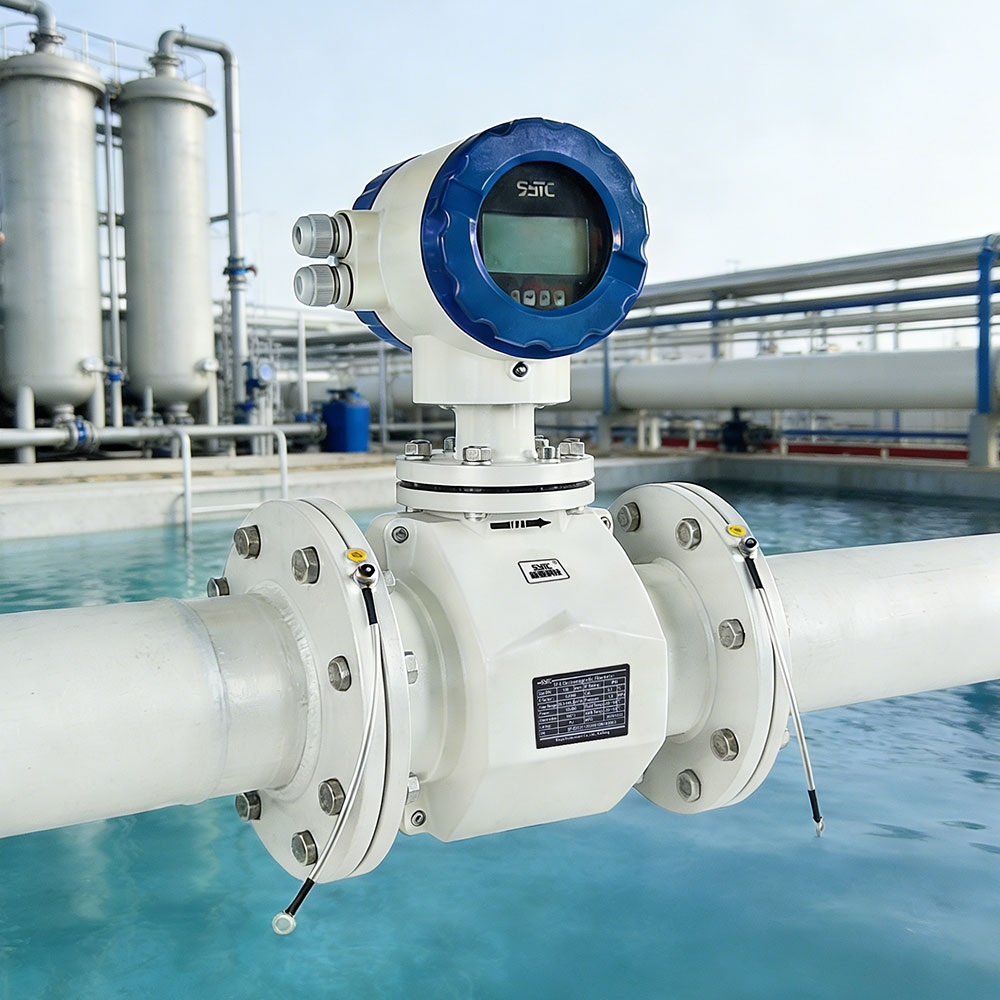
For sensors installed in pits, trenches, or areas subject to moisture ingress, an IP68-rated sensor housing supports submerged or buried installation. Converter housings are commonly rated IP65, IP66, or IP67, which should be matched to the specific mounting environment — indoor mechanical room, outdoor substation enclosure, or exposed pipeline trench.
Installation Environment
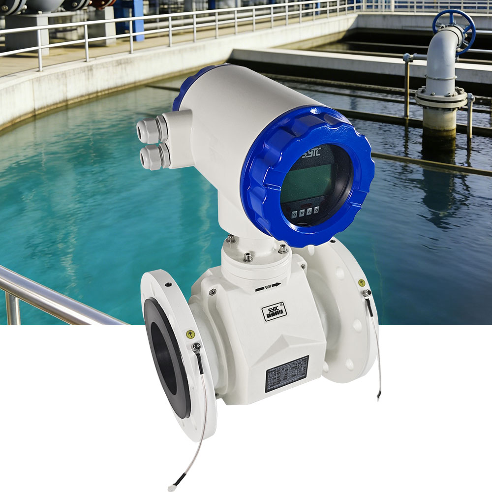
Heating network flow meters are often installed in confined mechanical rooms, underground chambers, or along exposed above-ground piping. Installation environment affects the choice between integral (sensor and converter combined) and split-type (converter mounted separately) configurations, as well as cable routing and accessibility for maintenance.
Grounding
Proper grounding of both the sensor body and the connecting pipeline is required to prevent stray electrical potential from distorting the induced signal. This is particularly important in heating networks with cathodic protection systems or where the pipeline shares grounding infrastructure with other electrical equipment.
Full-Pipe Operation
Electromagnetic flow meters require the pipe to remain fully filled with liquid at the measurement point to generate an accurate signal. Empty-pipe conditions — which can occur during partial-load operation, air pocket formation, or improper vertical installation — will compromise accuracy. Self-diagnosis functions that detect empty-pipe conditions, excitation circuit breaks, and flow range overflow help operators identify these conditions quickly rather than relying solely on downstream data anomalies.
Calibration
Calibration should reflect the actual installation conditions, including pipe orientation, upstream/downstream straight-pipe requirements, and expected conductivity range. Factory-calibrated replacement circuit boards that preserve original accuracy settings simplify field maintenance without requiring a full recalibration cycle after electronics replacement.
Common Challenges and Engineering Solutions
High-Temperature Operation
Continuous exposure to elevated supply-line temperatures accelerates aging of lining and electrode seals. Solution: select lining and electrode materials rated for the network's actual maximum operating temperature, and consider split-type installation to keep converter electronics in a cooler ambient location.
Air Entrainment
Air pockets introduced during system fill, venting, or pump cavitation can create intermittent empty-pipe conditions. Solution: install the sensor in a pipe orientation (typically vertical with upward flow, or a filled horizontal run) that minimizes air accumulation at the measurement point, and use empty-pipe self-diagnosis to flag anomalies.
Insufficient Full-Pipe Conditions
Low-load operation (e.g., overnight or shoulder-season demand) can reduce flow to levels where the pipe is not consistently full. Solution: verify minimum expected flow against the sensor's full-pipe requirement during the design stage, and locate the sensor where gravity and pipe geometry favor continuous full-pipe flow.
Flow Fluctuations
Pump staging, valve modulation, and load-following operation in district heating networks create rapid flow changes. Solution: rely on the meter's real-time signal processing chain and bidirectional measurement capability to track fast transitions accurately, and confirm the converter's response time is adequate for the network's control loop.
Improper Installation
Insufficient upstream/downstream straight-pipe length, incorrect grounding, or misaligned flanges are common field errors. Solution: follow manufacturer installation guidance precisely, confirm flange compliance with applicable standards such as GB/T9124.1-2019, and verify grounding continuity during commissioning.
Changes in Water Conductivity
Seasonal water treatment adjustments or make-up water addition can shift conductivity. Solution: confirm the meter's operating conductivity range during selection and periodically verify signal stability during commissioning across different seasonal water conditions.
Installation and Maintenance Recommendations
- Allow the recommended preheating/warm-up period (commonly around 10 minutes) before taking readings after power-up, and follow standard operational guidance during commissioning.
- Establish a routine check of self-diagnosis alarms for empty pipe, excitation circuit faults, and range overflow as part of scheduled maintenance.
- For remote or hard-to-access installation points along a heating network, communication options such as RS485, HART, GPRS, or WiFi (STA/AP modes) allow centralized monitoring without requiring frequent physical site visits.
- Maintain records of parameter configuration using multi-level password protection to prevent unauthorized changes to calibration or measurement settings.
- Keep at least 120 months of internal accumulation data available for forward, reverse, and net flow, which supports historical trend review and billing verification disputes.
Flow Measurement vs. Heat Energy Calculation
It is important to distinguish flow measurement from heat energy (thermal) metering. An electromagnetic flow meter measures volumetric flow rate and accumulated volume — it does not, by itself, calculate delivered heat energy. Heat energy calculation requires a separate temperature measurement system (supply and return temperature sensors) combined with an enthalpy-based calculation module, consistent with heat measurement standards such as CJ128-2007. Some flowmeter product lines, such as battery-powered electromagnetic flow meters used in remote monitoring stations, include enthalpy difference (Δh) calculation functionality as an integrated but distinct capability alongside flow measurement. Project teams specifying heat metering — rather than flow monitoring alone — should confirm whether the selected device includes this combined temperature-and-flow calculation function or requires a separate heat calculator.
Supplier Evaluation Checklist
When evaluating suppliers for district heating water flow measurement equipment, engineering and procurement teams should confirm:
- Compliance with recognized standards, such as JB/T9248-2015 for electromagnetic flowmeters and GB/T9124.1-2019 for flange dimensions.
- Availability of protection ratings matching the installation environment (IP68 for sensors in wet or buried locations; IP65/66/67 for converters).
- Communication protocol support (RS485, RS232, HART, GPRS, Bluetooth, WiFi) and compatibility with MODBUS-RTU for integration into existing SCADA or building management systems.
- Availability of RESTful API / JSON data exchange for integration with an IoT big data platform or third-party monitoring software.
- Documented lining and electrode material options suitable for the network's actual temperature and water chemistry.
- After-sales support scope, including troubleshooting guidance for excitation and empty-pipe alarms, and factory-calibrated replacement components.
Kaifeng Xinya Instrument Co., Ltd. is one example of a supplier offering electromagnetic flow meter product lines — including standard industrial models, insertion-type sensors for large-diameter pipelines, and battery-powered units for remote monitoring — alongside an IoT Big Data Platform for centralized flow data management. Project teams should independently verify that any specific model's temperature, pressure, and material specifications match their district heating network's actual operating conditions before final selection.
Frequently Asked Questions
1. Can an electromagnetic flow meter measure district heating water directly?
Yes, provided the water conductivity falls within the meter's operating range, which is typical for treated district heating water. The meter measures volumetric flow; it does not by itself calculate delivered heat energy unless paired with a separate temperature sensing and enthalpy calculation module.
2. What pipe diameter range do electromagnetic flow meters cover for heating networks?
Full-bore electromagnetic flow meters commonly cover DN15 to DN3000, while insertion-type sensors offer a cost-effective alternative for very large-diameter mains where full-bore installation is impractical.
3. How does temperature affect electromagnetic flow meter accuracy in heating water applications?
Temperature can influence water conductivity and thermal stress on sensor components. Selecting lining, electrode, and housing materials rated for the network's actual supply and return temperatures, along with proper flange and grounding practices, helps maintain stable accuracy.
4. What happens if the pipeline is not always full during low-load periods?
Reduced or intermittent full-pipe conditions will compromise measurement accuracy. Empty-pipe self-diagnosis features can alert operators to this condition, and proper sensor orientation and location during installation help minimize its occurrence.
5. Do electromagnetic flow meters require regular recalibration in district heating service?
Calibration intervals depend on installation conditions and water chemistry stability. Verifying signal stability periodically, especially across seasonal conductivity changes, and using factory-calibrated replacement electronics when needed, supports long-term measurement reliability.
6. Can flow data from these meters integrate with existing SCADA or IoT monitoring systems?
Yes. Communication options such as RS485, HART, GPRS, Bluetooth, and WiFi, along with RESTful API/JSON support, allow flow data to be integrated into SCADA systems or centralized IoT monitoring platforms for district heating network oversight.
7. Is grounding really necessary for electromagnetic flow meters on heating pipelines?
Yes. Proper grounding of the sensor and connected pipeline prevents stray electrical interference from distorting the induced signal, which is especially important on networks with cathodic protection or shared electrical grounding infrastructure.
https://www.sytcflowmeter.com/
Kaifeng Xinya Instrument Co., Ltd.
