Sizing a Liquid Flow Calibration Bench by Min and Max Rates
Liquid Flow Meter Calibration Bench Sizing by Minimum and Maximum Test Flow Rates
Buyers should determine calibration bench capacity by the minimum and maximum test flow rates required for each meter size and type, not by nominal pipe diameter alone. A bench must deliver stable, repeatable flow across the full test range specified for the meter under test, match the operating range of the reference standard, and support the piping configuration needed for valid test points. Capacity should be confirmed against documented bench specifications, not assumed from DN labeling.
Why Nominal Pipe Diameter Alone Cannot Define Bench Capacity
Nominal diameter (DN) describes the physical connection size of a meter, not its flow measurement range. Two meters sharing the same DN can require very different minimum and maximum flow rates depending on meter type (electromagnetic, turbine, Coriolis, vortex), intended service (water, chemical, viscous liquid), and the velocity range the meter is designed to measure. A calibration bench sized only by pipe diameter may fail to reach the low-flow or high-flow test points a given meter actually needs, even though the physical connection fits.
Minimum, Normal, and Maximum Test Flow Rates by Meter Size and Type
Each meter size and type has its own minimum, normal (Qt/Qp-type midpoint), and maximum test flow rate requirements, typically defined by the meter manufacturer's data sheet or the applicable verification standard. These three points are not interchangeable:
- Minimum test flow rate verifies low-flow linearity and is often the most demanding point for bench stability.
- Normal (transitional/permanent) flow rate reflects typical operating conditions and is used for routine verification.
- Maximum test flow rate confirms performance near the meter's upper measurement limit and places the highest demand on bench pumping and piping capacity.
A bench capable of reaching the maximum flow rate for one meter type does not automatically guarantee stable performance at the minimum flow rate for a different meter type or diameter.
Why Stable Flow, Reference Standard Range, Piping, and Test Points All Matter
Flow capacity figures are meaningless without stability. A bench must generate flow that remains steady long enough for valid data collection at each test point. In addition:
- Reference standard operating range: the calibration method (static mass, master meter, sonic nozzle, etc.) and its reference instrument must itself be valid across the same flow range being tested.
- Piping arrangements: straight-pipe lengths, upstream/downstream fittings, and flow-conditioning requirements affect whether a given flow rate produces a representative test condition.
- Intended test points: buyers should define the actual test points needed (e.g., minimum, 0.1Qmax, Qt, Qmax) rather than request generic "full range" coverage, since not every bench configuration supports every point with the same confidence.
Why One Bench May Not Cover All Diameters and Flow Ranges Equally
A single calibration line is generally optimized for a defined diameter and flow-rate window. Extending coverage to much larger or smaller diameters, or to wider flow ranges, often requires different reference standards, piping sections, or separate calibration lines. A bench rated for small-to-medium diameters at laboratory-level conditions is not automatically suitable for very large diameters or industrial-scale flow rates, and vice versa. Performance (stability, achievable minimum flow, maximum flow) can vary across diameter segments even within the same facility.
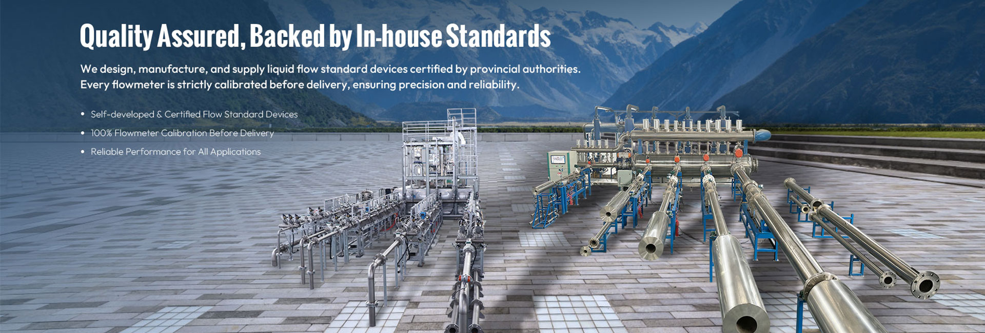
Sample Requirement Matrix (Illustrative Placeholders Only)
| Meter DN | Required Test Flow Range | Test Method (Example) | Items to Verify |
|---|---|---|---|
| DN15 | [Qmin]–[Qmax] placeholder | Static mass / master meter | Low-flow stability, repeatability |
| DN50 | [Qmin]–[Qmax] placeholder | Master meter method | Mid-range linearity |
| DN150 | [Qmin]–[Qmax] placeholder | Static mass method | High-flow stability, piping straight-run compliance |
| DN300+ | [Qmin]–[Qmax] placeholder | To be confirmed with supplier | Reference standard range match, facility capability |
Values above are placeholders for illustration only and must be replaced with verified figures from the meter manufacturer's documentation and the calibration provider's facility specifications.
Practical RFQ Checklist
- [ ] List each meter type and nominal diameter requiring calibration
- [ ] State the required minimum, normal, and maximum test flow rates per meter size
- [ ] Specify target measurement uncertainty for each test point
- [ ] Identify preferred or required calibration method
- [ ] Confirm available utilities (water supply, power, drainage, space)
- [ ] Request documented bench flow-rate capability and reference standard range
- [ ] Clarify piping and straight-run requirements for each meter size
- [ ] Ask whether all required diameters/flow ranges can be covered on one line or require multiple setups
FAQs
Q1: Can one calibration bench test both very small and very large diameter meters?
Not always. Coverage depends on the bench's documented flow-rate range and reference standard capability; some facilities split small and large diameters across separate lines.
Q2: Does a high maximum flow rate guarantee good low-flow performance?
No. Minimum flow stability is a separate capability from maximum flow capacity and should be verified independently.
Q3: Is calibration bench capacity the same as meter accuracy?
No. Bench flow capacity defines what flow conditions can be generated and measured; meter accuracy is a separate attribute of the device under test, confirmed through the calibration process itself.
Q4: What information should buyers provide to get an accurate capacity assessment?
Meter types, nominal diameters, required minimum/normal/maximum test flow rates, target uncertainty, preferred calibration method, and available site utilities.
Conclusion
Sizing a liquid flow calibration bench requires matching documented minimum, normal, and maximum test flow rates for each meter type and diameter against verified bench and reference standard capabilities — not relying on nominal pipe diameter as a proxy. Because capacity and stability vary by diameter segment and meter type, buyers should treat each required test point as a distinct requirement.
For technical evaluation, share your meter types, nominal diameters, required test flow rates, target uncertainty, calibration methods, and available utilities so that bench suitability can be assessed against documented specifications.
https://www.sytcflowmeter.com/
Kaifeng Xinya Instrument Co., Ltd.
