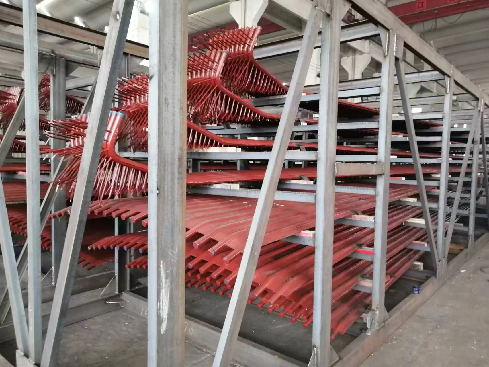
Water-cooled (membrane) wall
https://www.shuangmane.com/Water-cooled-wall.html
https://www.shuangmane.com/Water-cooled-membrane-wall.html

A waterwall in a boiler is an furnace wall that is comprised of refractory and tubes in a water-tube boiler.The tubes are evenly spaced and generally connect to headers which in turn are connected back to the main generating bank of the boiler.
|
Name |
Membrane water panel |
|
Material |
Carbon steel,Alloy,Stainless steel |
|
Tube size |
Φ38 - 76 mm, Customize |
|
Standard |
ISO , ASME |
|
Model |
Studded |
|
Application |
Istallable around the boiler combustion chamber |
A waterwall in a boiler is an furnace wall that is comprised of refractory and tubes in a water-tube boiler.The tubes are evenly spaced and generally connect to headers which in turn are connected back to the main generating bank of the boiler.They serve a two fold purpose here in that capture heat that would otherwise escape to the atmosphere and help heat the water in the boiler.And they also help keep the refractory cool(relatively speaking)This prevents spalling of the refractory.
Membrane/Water Wall Material and Arrangement:
The furnace and roof are made up of membrane water wall and hung on the steel structure by upper hanging suspender of water cooling upper header. Furnace intersecting surface is 3170×5290mm2 and the elevation of top furnace is 28877mm. The membrane water wall is made up of φ60×5 and 6×45 welding steel flat. The combustion chamber is made of φ60×4 steel tube and welded with pin to fasten refractory material. The upper part of combustion chamber connects with furnace membrane water wall. The lower part connects with water cooling wind chamber and water cooling air distributor. The water cooling wind chamber is made up of φ60 steel tube and welded with pins to fasten the refractory material. The water cooling distributor is welded with φ60 steel tube and 6X45 steel flat. The small holes on the steel flat connects with the funnel cap.
The furnace divides left, right, front and back water circulation circuit. The steam leading tube is made up of φ133×5 and φ108×4.5 steel tube. The downcomer is made up of φ108×4.5 steel tube. Install the blowdown valve under the lower header to periodic blow down.
Vivi
liulaikou00@126.com