Busbar Isolation Strategies for Lithium Battery Pack Design
The Engineering Challenge in High-Voltage DC Systems
High-voltage lithium battery packs present a uniquely demanding environment for electrical insulation. Unlike conventional AC switchgear, where current periodically crosses zero and naturally interrupts any arc event, DC systems operating at 1,000V to 1,500V sustain continuous arc energy once a discharge is initiated. This absence of a zero-crossing point means that surface tracking along busbar insulators can become self-sustaining and catastrophic.
The challenge intensifies in battery energy storage systems (BESS) and EV battery pack architectures, where thermal loading, mechanical vibration from transport or seismic events, and ultra-dense module-to-module layouts must all be accommodated within a single compact enclosure. Engineers must simultaneously address three interdependent variables: creepage distance, clearance distance, and physical compactness — and compromising any one of them introduces measurable safety and reliability risk.
Understanding Creepage, Clearance, and Why Both Matter
Creepage distance refers to the shortest path along the surface of an insulator between two conductive parts. Clearance distance is the shortest path through air. Both are governed by system voltage, pollution degree, and overvoltage category, as defined under IEC 60664-1.
In lithium battery pack environments, pollution from condensation, dust, and electrolyte vapor can deposit conductive films on insulator surfaces. If creepage distance is insufficient, these films create low-resistance paths that progressively carbonize the insulator surface — a phenomenon quantified by the Comparative Tracking Index (CTI). Materials with a CTI of 600V or higher are classified as Material Group I, meaning they carry the highest resistance to forming conductive carbon tracking under contamination.
Clearance, meanwhile, must account for transient overvoltages. Per IEC 60664-1, installations in Overvoltage Category IV environments should withstand 1.2/50 μs impulse overvoltages up to 8 kV. Any standoff insulator used within the battery pack must maintain its dielectric integrity under such surge events without puncture or flashover.
The Compactness Constraint: Why Standard Designs Fall Short
Battery pack designers face a fundamental tension. Increasing creepage and clearance distances typically requires larger insulators or greater physical spacing — but BESS racks and EV modules are optimized for maximum energy density, leaving minimal room for bulky support hardware.
Traditional solutions often require either custom engineering that adds design cycle time, or oversized insulators that consume volume budgeted for active cells. Neither outcome serves modern pack integration requirements. The answer lies in insulator geometry and material science working together: a ribbed or hexagonal-base design can extend the effective creepage path by 35% to 60% without increasing the overall installation height or footprint. This geometric efficiency allows engineers to satisfy IEC 60664-1 creepage requirements within the same enclosure volume constraints they already face.
Material Selection: The Critical Role of BMC, SMC, and Epoxy
Not all insulating materials perform equally under the combined thermal, mechanical, and electrical stresses of a lithium battery environment. Three material systems dominate engineered insulator design for these applications:
-
BMC (Bulk Molding Compound) and DMC (Dough Molding Compound): Thermoset composites offering CTI of 600V or higher, UL 94-V0 flame retardancy, and operating temperature ranges from -40°C to +140°C. These properties are directly relevant to battery containers that experience thermal cycling, where insulator embrittlement or softening would compromise mechanical clamping forces on busbar joints.
-
SMC (Sheet Molding Compound): Uses longer glass fibers (25 mm to 50 mm) for superior flexural and tensile strength. In high-current busbars subjected to electromagnetic shockwaves during short-circuit events, SMC-based supports resist the electrodynamic repelling forces that would cause standard insulators to crack or mechanically displace.
-
Vacuum-Cast Epoxy Resin: For medium-voltage applications extending into ring main units and VFD environments, void-free epoxy castings produced via automated pressure gelation (APG) achieve volume resistivity greater than 10¹⁴ Ω·cm, partial discharge below 5 pC at 1.1 Um, and dielectric loss angle tan δ no greater than 0.005 at 20°C.
The coefficient of thermal expansion (CTE) is equally critical: busbar insulators must expand and contract at a rate compatible with copper (16.5 × 10⁻⁶ /K) and aluminum (23.1 × 10⁻⁶ /K) conductors. Engineered composites with a CTE of 15–22 × 10⁻⁶ /K minimize differential expansion stress at mounting interfaces during repeated thermal cycling — a failure mode that accumulates invisibly over service life before resulting in a loss of electrical isolation.
DOWE Electric's Engineering Approach to High-Voltage DC Isolation
DOWE Electric (Yueqing City Duwai Electric Co., Ltd.), headquartered in Liushi Town, Yueqing Economic Development Zone, Zhejiang Province, China, has spent over two decades developing insulation solutions for global power distribution infrastructure. The company's SB/JYZ Series standoff insulators are purpose-designed for high-voltage DC environments — specifically solar PV inverter DC links, BESS storage cabinets operating at up to 1,500V DC, lithium battery pack module-to-module busbar interconnects, and EV fast charging infrastructure.
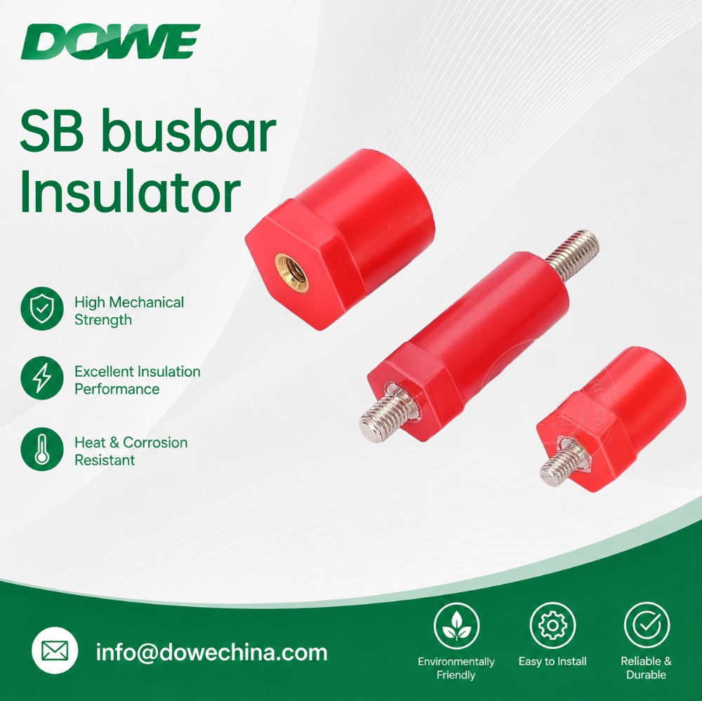
The SB/JYZ Series features a hexagonal anti-rotation base integrated with a cylindrical upper body. This geometry serves a precise mechanical function: it allows assembly technicians to hold the base with an open-end wrench while applying full tightening torque, preventing rotational shear stress from transferring to the battery module mounting plate. Thread sizes range from M5 through M16, with tensile pull-out resistance exceeding 8,000 N for M8/M10 inserts, and torsional lock greater than 1.5× the bolt proof torque.
The dimensional range — body diameters from 14 mm (SB14/JYZ-14) through 60 mm (SB60/JYZ-60), with heights spanning 14 mm to 90 mm — gives pack designers a complete height ladder that accommodates varying enclosure depths without requiring custom tooling. The SB20 (JYZ-20), for instance, covers sixteen height increments from 16 mm to 90 mm within a single product family, supporting flexible busbar-to-backplate specifications across different battery module configurations.
DOWE supports design verification efficiency: SGS third-party type test reports are available for battery pack integrators and panel builders to reference directly in Design Verification documentation, without independent destructive testing. The SB/JYZ Series carries UL 94-V0 certification with afterflame time no greater than 8 seconds and zero flaming drips — a specification that directly addresses NFPA 855 battery energy storage fire safety requirements. RoHS 2011/65/EU, 2015/863, and REACH (EC 1907/2006) compliance enables frictionless European and North American market entry.
Dielectric Withstand and Impulse Performance
For low-voltage BESS applications, the SB/JYZ standoffs are rated to withstand 3,500V AC (50 Hz, 1 minute) without puncture or flashover, and sustain 1.2/50 μs impulse overvoltage up to 8 kV, placing them within Overvoltage Category IV per IEC 60664-1. These figures are validated through DOWE's in-house certified high-voltage dielectric test laboratory, establishing a documented performance baseline rather than relying on supplier self-declaration.
Integrating Isolation Strategy into Pack-Level Design
A robust busbar isolation strategy in a high-voltage lithium battery pack is not achieved through insulator selection alone. It requires a systems-level approach that addresses each variable in sequence:
- Geometry selection: Ribbed or hexagonal profiles that extend creepage path by 35% to 60% without adding installation height
- Material qualification: CTI ≥ 600V Material Group I, UL 94-V0 self-extinguishing behavior, and CTE alignment with copper and aluminum conductors
- Mechanical interface design: Anti-rotation bases and pull-out resistance exceeding 8,000 N to maintain isolation geometry under vibration and thermal cycling
- Regulatory compliance: IEC 60664-1 overvoltage category matching, RoHS and REACH environmental compliance for international deployment, and UL 94-V0 for fire code alignment
DOWE Electric's manufacturing infrastructure — encompassing automated BMC/SMC hydraulic compression molding workshops, vacuum casting facilities for epoxy resin using APG, and automated CNC thread tapping units — supports a production capacity greater than 500,000 low-voltage standoffs per month. The company exports millions of SB/JYZ insulators annually to solar inverter OEMs, battery pack integrators, and switchgear builders across Germany, the United States, Spain, Italy, the Netherlands, and Canada, with overall market coverage spanning more than 60 countries. That scale of validated international adoption reflects the degree to which this engineering approach has been accepted by the global energy storage and EV charging industries.
http://www.busbarinsulator.com
Yueqing City DUWAI Electric Co.,LTD
