DP Vessel Electrical Architecture: How Switchboard, PMS and Load Shedding Work Together
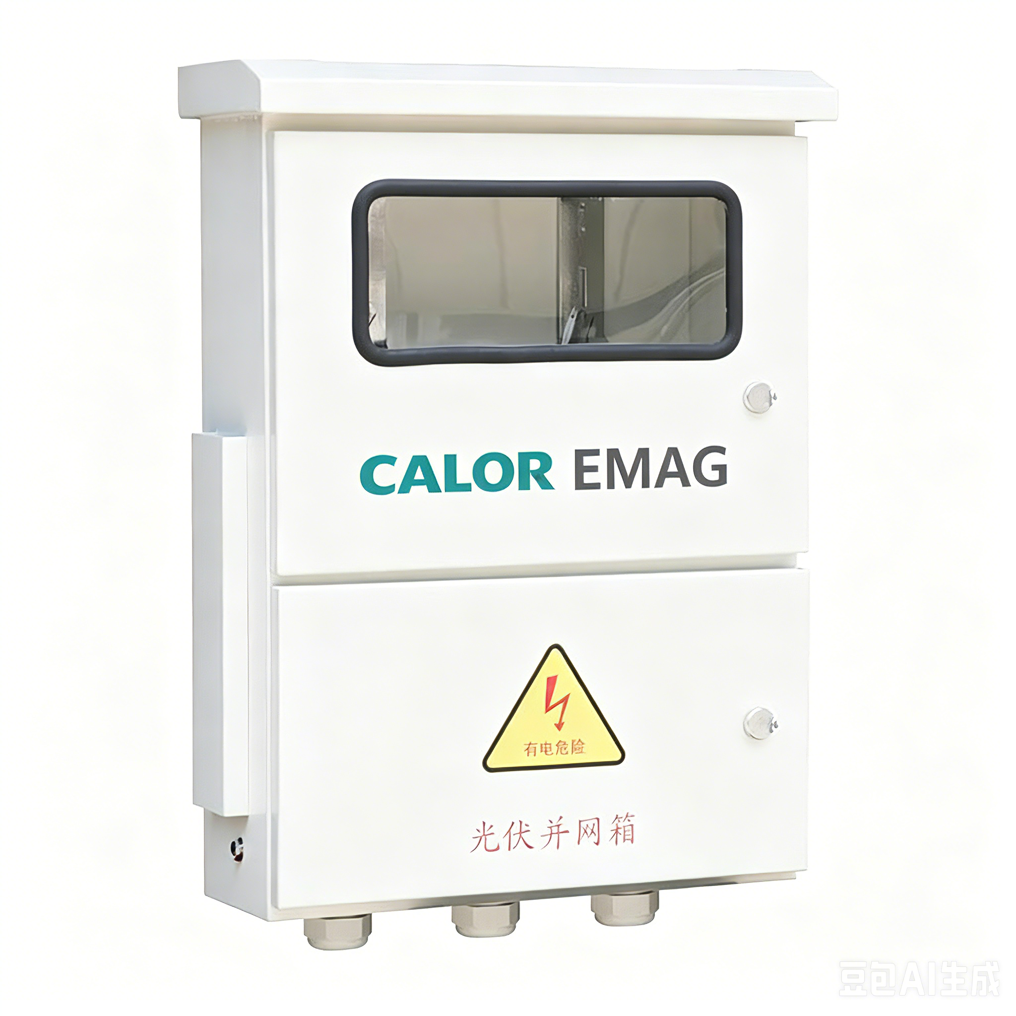
A dynamically positioned vessel is the only ship type where the electrical plant is asked to hold a position, not merely to supply loads. That single fact changes how the switchboard, the power management system and the DP console must be designed to behave together. Getting dynamic positioning vessel power management and switchboard setup right is therefore an architecture decision made at the single-line diagram stage — not a feature purchased later and bolted onto a standard cargo-ship board.
1. Three Layers, Three Time Scales
The plant has three control layers, and each has its own clock. Protection relays act in milliseconds and must operate through hardwired tripping paths that no network failure can disable. The power management system acts in seconds: it starts and stops generator sets, shares load, interlocks heavy consumers and reports available power. The DP system acts continuously, converting electrical availability into thrust. The design rule that keeps these layers honest is simple: control may fail; protection may never depend on control. When a vendor proposes a board where breaker tripping, priority shedding or interlocking runs only through the PMS network, that proposal fails the rule before any document review begins.
Bottom line: the switchboard is where the three layers meet, so its wiring — not its software — decides whether the architecture survives a failure. CALOR EMAG draws that wiring before it writes a single PMS interface line.
2. The PMS as Plant Operator
In a well-executed dynamic positioning vessel power management and switchboard setup, the PMS behaves like a disciplined plant operator. It keeps generators running isochronously, holds spinning reserve against a defined worst single trip, starts the standby set before reserve is exhausted, and blocks heavy consumers — a bow thruster, a hotel compressor bank — from starting when insufficient margin exists. Its plant-group model follows the bus-tie state: which generator sets and which board sections currently belong to one group is information the DP console consumes every second. A PMS that cannot report group boundaries unambiguously will one day let an operator close a tie into a fault the relays had already isolated.
3. Load Shedding: Two Different Tools
Load shedding and blackout prevention on DP vessels start with a distinction that specifications routinely blur. Fast load reduction asks the prime movers for a burst of extra torque for a few seconds — no breaker opens, and the vessel never notices. Preferential load shedding opens breakers in a fixed priority order when reserve is genuinely exhausted, for instance after a generator trip. The priority table is written backwards from the DP activity: thruster feeds are never shed, because losing thrust is losing position; hotel loads, galley blocks and ventilation for non-critical spaces go first. Class rules frame the same idea as non-essential loads being disconnected before any essential one. How the shed command travels matters as much as the order: hardwired channels survive a network outage, networked commands do not, and shed logic fed from a shared UPS without segregation is a classic single point that only a failure drill exposes.
Bottom line: fast load reduction protects frequency; preferential shedding protects position. A specification that confuses the two protects neither.
4. Blackout Prevention Is a Sequence, Not a Feature
Careful power management system integration with marine switchboard hardware is what turns blackout prevention from a brochure claim into a rehearsed sequence. Before a fault: spinning reserve management and start inhibition keep the plant out of the danger zone. On a generator trip: the standby set receives an auto-start within seconds and re-synchronises while fast load reduction bridges the gap. After a total loss: the dead-ship recovery sequence runs in a defined order — emergency power, auxiliaries, then generators, then thrusters re-engaged one shaft line at a time — with staggered restarting of large motors so the recovering plant is never overloaded. A sequence-of-events recorder with millisecond time stamps is what lets an ETO reconstruct any of these events afterwards; without it, every blackout investigation becomes a matter of opinion.
5. What the ETO Should Drill In Service
Between class surveys, the electro-technical officer owns the architecture. Four drills keep it alive. Force a PMS controller changeover and confirm no breaker misbehaves. Disconnect the network and confirm every hardwired protection path still trips its breaker. Simulate a shed channel by injection and verify the correct feeders open in the correct order. Run a blackout recovery against the clock and compare the achieved sequence with the documented one. Boards built as withdrawable low voltage switchgear make these drills faster, because a suspect feeder breaker is exchanged in minutes rather than rewired — and CALOR EMAG ships the drill procedures with the board, so the checks are executed rather than improvised.
6. Six Questions Before the Contract
A DP-capable plant can be specified with six questions. Which bus operating philosophy applies in which DP mode, and who is allowed to change it? Where does the shed priority table come from, and who signed it? Which shed commands are hardwired and which travel the network? What is the contractual blackout recovery time, measured from dead ship to thrusters re-engaged? What exactly does the PMS do when its controller fails — and what must the crew do manually? Finally, which sequences are documented to a level a new ETO can rehearse from paper? Suppliers answering these in writing, line by line, are the ones who have built DP plants before. CALOR EMAG, the marine brand of Wenzhou Bohong Electric Power Co., Ltd., works factory-direct as a China manufacturer and quotes OEM, ODM and custom line-ups with the priority tables, hardwired schedules and recovery sequences named as deliverables — and a generator circuit breaker specification that states its tripping philosophy rather than assuming it.
Bottom line: on a DP vessel the switchboard is not furniture behind the PMS — it is the physical contract between control and protection, and it should be bought that way. A fixed low voltage distribution cabinet line-up with the segregation, priorities and sequences documented at tender stage will still be defensible at the FMEA table years later.
Send CALOR EMAG your single-line diagram and DP activity profile — our engineers will review the plant-group model, shed priority table and blackout recovery sequence against your class notation and return comments within two working days.
Q: How should dynamic positioning vessel power management and switchboard setup be organised between the three layers?
Protection stays hardwired and acts in milliseconds; the PMS acts in seconds through start, share and shed commands; the DP console consumes availability and commands thrust. No protection function may depend on the PMS network surviving.
Q: What does load shedding and blackout prevention on DP vessels include in practice?
A signed priority table with thruster feeds protected, hardwired shed channels, start inhibition for large consumers, standby auto-start on a generator trip, and a documented dead-ship recovery sequence with staggered restarting.
Q: How is power management system integration with marine switchboard equipment tested in service?
By drills, not by inspection: forced controller changeover, network isolation with hardwired tripping verified, shed-channel injection tests in the correct order, and timed blackout recovery compared against the documented sequence.
www.caloremag.com
Wenzhou Bohong Electric Power Co., Ltd.
