How Does a Stretch Film Machine Work? XHD Explains Process
Core Conclusion: The working principle of a stretch film machine can be summarized as a physical rheological chain: PE pellets are plasticized by heat and shear in the extruder → the melt is distributed uniformly across the width through a T-die → the high-temperature melt film is quenched and set on a chill roll → thickness is measured inline and edge trim is cut → the film is wound under controlled tension. At every stage of this chain, there is a key engineering variable that determines film performance and production cost: plasticization uniformity determines gel spots and clarity; die lip gap and die temperature determine transverse thickness uniformity; chill roll temperature control determines crystallinity and tensile strength; changeover method determines effective output time. XHD's machinery responds to these five stages with specific, verifiable engineering: a barrier screw for ultra-high plasticization, in-house machined chill rolls with surface temperature variation ≤±1℃, a four-shaft servo system achieving 1-second instantaneous changeover with a complete cycle under 40 seconds, 380 m/min design line speed, 380–450 kwh/ton actual energy consumption, and online edge trim recycling through forced crushing and refeeding. These are not abstract performance claims—they are engineering facts that can be checked on a trial run with a thickness gauge, electricity meter, and stopwatch.

1. First, See the Whole Chain: Five Physical Stages of Stretch Film Production
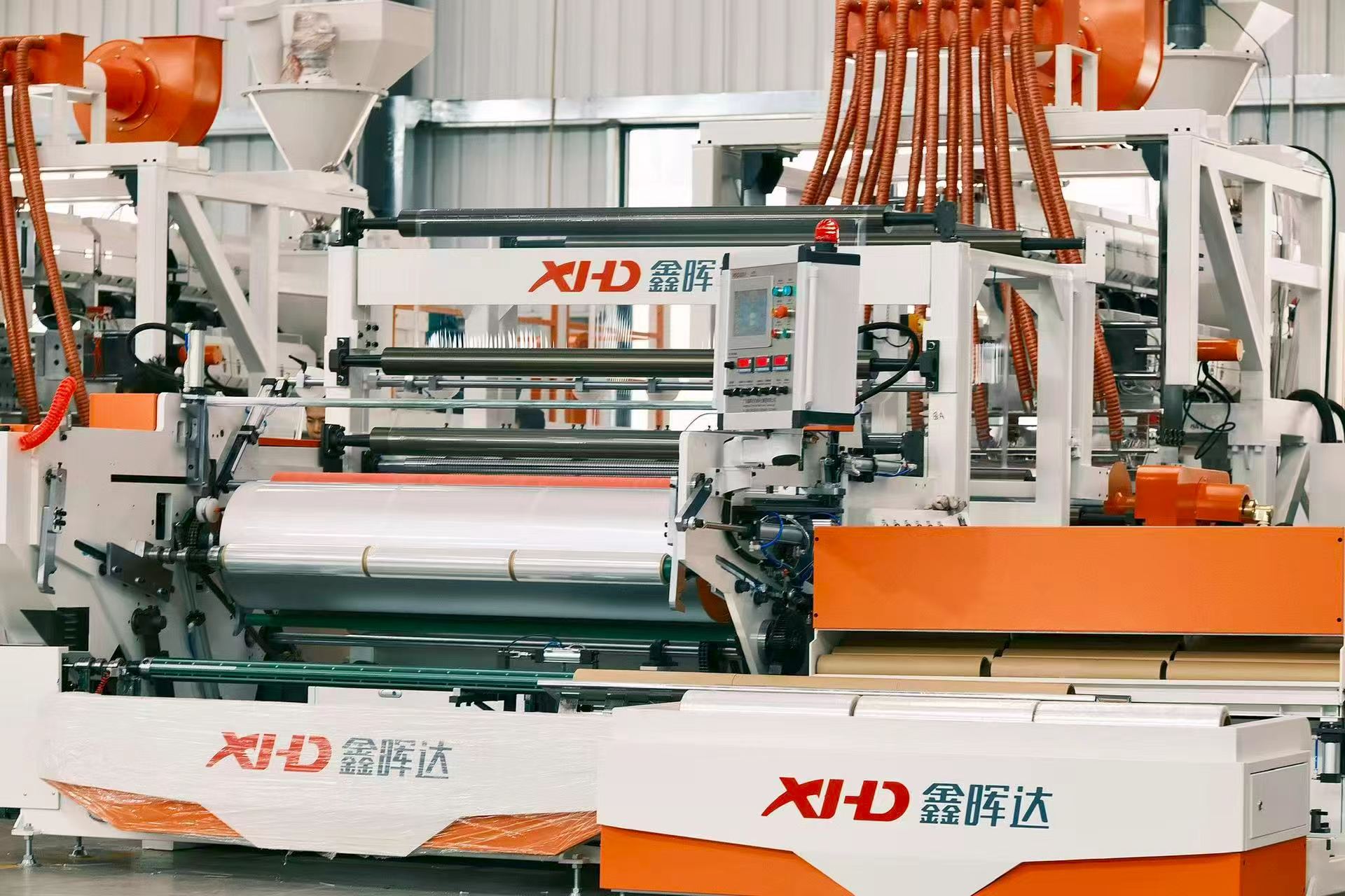
Stretch film equipment primarily adopts the flat-die cast film process route. Its core flow can be broken down into five sequential stages:
Stage One: Resin plasticization. PE pellets (LLDPE, mLLDPE, etc.) are fed into the extruder barrel, where the mechanical shear generated by the rotating screw, combined with conduction heat from external heater bands, gradually melts and homogenizes them into a rheologically stable polymer melt.
Stage Two: Die distribution and extrusion. The melt passes through a screen changer to filter out contaminants, then is conveyed to the T-die. The die lip gap directly determines the initial cross-sectional dimensions of the melt curtain exiting the die—the "starting point" of film thickness.
Stage Three: Quenching and setting. The high-temperature melt film falls as a suspended curtain onto the surface of a high-speed rotating chill roll, cooling to below the glass transition temperature in an extremely short time. Crystallization growth is suppressed, forming a structure with fine, uniformly distributed crystallites.
Stage Four: Thickness measurement and edge trimming. The set film passes through an inline thickness gauge that scans transversely, feeding thickness data back to the control system. The naturally thickened "thick edges" on both sides, caused by edge effects, are cut off by trimming knives, and the edge trim is crushed and fed back into the extrusion system.
Stage Five: Winding and changeover. The film is wound onto paper cores under precisely controlled tension. Winding tension that is too high causes excessive internal stress and crushed cores; too low results in staggered edges and loose rolls. The changeover method (manual, semi-automatic, fully automatic) directly determines the line's effective output time.
The working principle of a stretch film machine is not "a machine spinning"—it is a physical chain from melt rheology to roll mechanics being simultaneously controlled at five nodes.

2. Stage One: Plasticization — Why Screw Design Determines Whether the Film Has Gel Spots
Plasticization is the starting point of the entire chain, and the true source of many film-surface defects that seem to have "no identifiable cause." If PE pellets are not completely melted and homogenized in the screw, unmelted particles enter the die and form gel spots (fish eyes) on the film, directly reducing yield and downstream wrapping success rate.
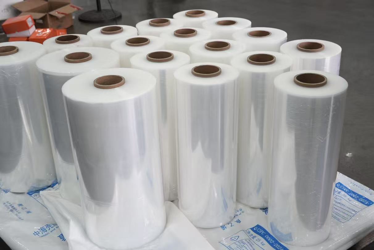
XHD's engineering configuration at this stage is high-speed screw melting technology, publicly stated to involve technical cooperation with an Italian company, drawing on barrier screw design to achieve ultra-high plasticization and a technical throughput increase of over 30%. The core logic of the barrier screw lies in separating the solid bed from the melt in different screw zones, preventing unmelted particles from being "carried" into the metering section. For high-clarity cling film or ultra-thin stretch film production, this design directly correlates with yield.
The die material is imported special mold steel, precision-machined to ensure long-term deformation resistance and stable, flat extrusion. The extrusion system uses alloy screws and barrels with nitriding treatment, paired with an imported static mixer to further improve melt color uniformity and plasticization quality.
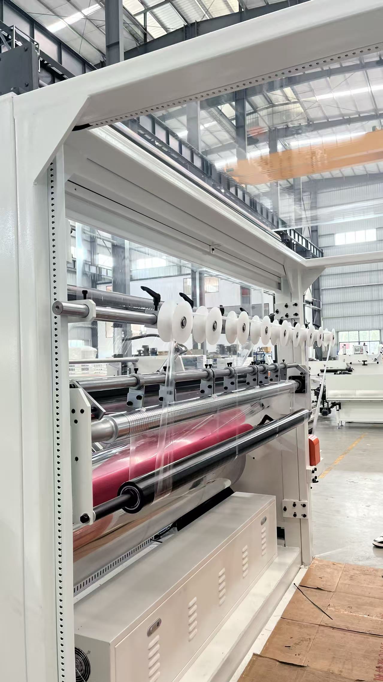
How to verify at this stage: During a trial run, use your target resin and sample the film surface after continuous operation to observe the number of gel spots. If gel spots are frequent, the problem is most likely in the plasticization section—not the die or cooling.
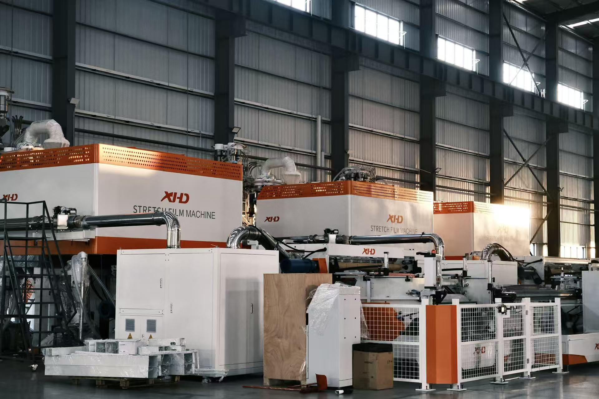
3. Stages Two and Three: Die Extrusion and Quenching — Where Thickness and Clarity Are Decided
3.1 Die Lip Gap: The "First Gate" for Transverse Thickness
When the melt exits the T-die, the uniformity of flow across the film width is determined jointly by the die lip gap and the internal flow channel design. If the die lip gap is inconsistent across the width, the melt flow on the wider side is greater, manifesting directly as transverse thick-and-thin bands in the film.
XHD's T-die adopts a special double-throttling design for more accurate film thickness; it can also be optionally equipped with a fully automatic die adjustment system and an APC-controlled automatic thickness gauge for inline thickness measurement and automatic die adjustment. The significance of this configuration is that thickness control shifts from "set once at startup" to "continuously closed-loop corrected during operation."
3.2 Chill Roll: The Common Source of Clarity, Tensile Strength, and Thickness Uniformity
Quenching and setting is where the cast film process fundamentally differs from blown film, and it is the key control point determining the film's physical properties. When the high-temperature melt tightly contacts the chill roll with circulating cooling medium, the temperature drops in an extremely short time. PE molecular crystallization growth is rapidly suppressed, forming a structure with fine, uniformly distributed crystallites—the physical underlying logic for stretch film possessing both good light transmittance and high elongation at break.
Conversely, if the chill roll's internal water channel design is flawed, or the chiller's cooling flow fluctuates, transverse temperature variation across the roll surface becomes excessive, causing uneven cooling shrinkage and inconsistent longitudinal tensile strength. Therefore, the machining precision and temperature control capability of the chill roll are hard indicators of the equipment's thermal performance.
XHD's engineering configuration at this stage includes:
-
Cooling steel rolls with internal two-way circulation design and built-in spiral flow channels, ensuring uniform roll surface temperature.
-
Chill rolls are machined in-house, not outsourced standard components, with ±1℃ temperature control precision; paired with rapid cooling and setting technology, improving transverse and longitudinal tensile strength by over 20%.
-
Negative pressure compensation technology: the film instantaneously adheres to the chill roll with zero gap for cooling and setting, avoiding surface defects.
The clarity and tensile strength of a film are not "tuned" in the formulation—they are "rozen" in the fraction of a second when the melt touches the chill roll. Every degree of deviation in roll surface temperature costs one increment of performance consistency across the film width.

4. Stage Four: Thickness Measurement and Edge Trimming — Edge Trim Is Not Waste; It Is Raw Material That Can Be Re-fed Online
After exiting the die lip, the cast film naturally thickens on both sides due to edge effects and must be trimmed to ensure flat winding edges on the master roll. For a 2000mm width line, edge trim typically accounts for 5–8%. Low-cost equipment commonly treats edge trim as waste for sale or disposal; online recycling means this material returns to the extrusion system in near-virgin form.
XHD's edge trim recovery configuration is a high-speed edge suction device with forced crushing and feeding, achieving stable online recycling and reducing waste. The recovered trim is crushed and conveyed via air duct directly back to the extruder feed section, where it is blended with virgin material in real time. For a film plant producing 10 tons daily with a 6% edge trim rate and 300 operating days, the raw material cost difference between online recycling and scrap sale accumulates at the hundred-ton level.
Simultaneously, the inline thickness gauge scans transversely before winding, capturing thickness deviations at micron-level resolution and feeding data back to the machine control system. Whether this data is used only for "display" or can be "linked to die control" is a verifiable engineering detail worth asking about.
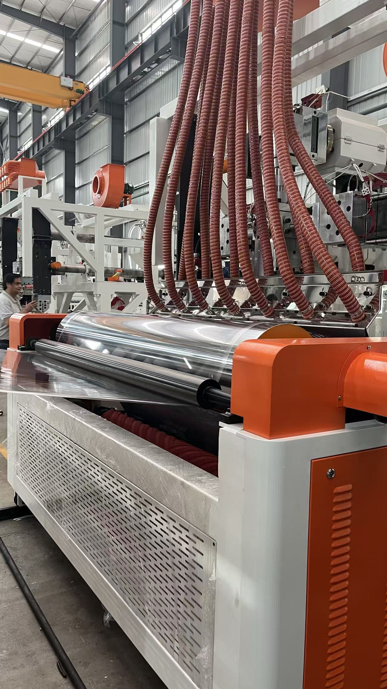
5. Stage Five: Winding and Changeover — Why "That One Second of Changeover" Determines the Line's Effective Output
Winding is the most mechanically complex and stability-critical stage in a stretch film machine. The film must be wound onto paper cores under precisely controlled tension: too high, and excessive internal stress causes crushed cores; too low, and edges stagger and rolls become loose.
But the more critical variable is the changeover method. Conventional dual- or three-shaft winding requires speed reduction or stopping during changeover, and every stop brings scrap film, energy consumption, and lost effective output time. The industry classifies changeover methods into three types: single/dual-shaft manual, three-shaft semi-automatic non-stop, and four-shaft high-speed fully automatic intelligent changeover. Mechanical structure differences directly determine the line's maximum speed, daily output, and labor input.
XHD's four-shaft intelligent high-speed line configuration at this stage is:
| Configuration | Published Data | Engineering Implication |
|---|---|---|
| Four-shaft servo changeover | 1-second instantaneous changeover, all four shafts precisely repositioned on the same horizontal plane | Cutting action does not reduce line speed |
| Complete changeover cycle | <40 seconds | Effective output time is preserved |
| Automated operations | 10 operations (automatic roll change, film removal, core loading, deflation, inflation, film threading, recovery, monitoring, weight compensation, feeding) | No manual intervention during changeover |
| Flying knife technology | Cutting at full production speed, without slowing or stopping | Differs from conventional blade cutting that requires slowdown/stop |
| Winding tension | Advanced torque motor with four-shaft automatic tension control | Tension matched to film thickness, width, and line speed |
The difference between flying knife technology and conventional blade cutting deserves separate mention: conventional cutting requires the line to slow down or stop completely on each cutting cycle; flying knife technology allows the cutting action to be completed while running at full speed—no slowdown, no stop. For a four-shaft line with 380 m/min design speed, whether line speed drops during changeover creates a hundred-ton-level output gap annually.
The “high speed” of a high-speed line is not how fast it runs when idling—it is whether the line speed needle drops during that one second of changeover.
6. Summary of Verifiable Parameters Across the Five Stages
The engineering configurations at the five stages can be summarized in a comparable table:
| Process Stage | Engineering Variable | XHD Configuration & Published Parameters | Impact on Film/Cost |
|---|---|---|---|
| Plasticization | Screw design, plasticization uniformity | Barrier screw technology, 30%+ technical throughput increase; imported mold steel die | Gel spot control, clarity |
| Die extrusion | Die lip gap, transverse flow uniformity | T-die double-throttling design; optional APC automatic thickness measurement and die adjustment | Transverse thickness tolerance |
| Quenching and setting | Chill roll temperature control, adhesion method | In-house machined chill rolls, ±1℃; negative pressure zero-gap adhesion | Clarity, tensile strength, thickness uniformity |
| Thickness measurement & trimming | Inline thickness gauge, edge trim recycling | Inline thickness gauge; high-speed edge suction + forced crushing online refeeding | Raw material utilization, scrap cost |
| Winding & changeover | Changeover method, tension control | Four-shaft servo 1-second changeover, cycle <40 seconds; 10 automated operations; flying knife full-speed cutting | Effective output time, labor cost |
At the complete line level, XHD's four-shaft high-speed line publishes: design line speed 380 m/min, maximum winding diameter φ350mm, actual energy consumption 380–450 kWh/ton, output 13–15 tons/day (2000mm width), one-person operation with one-key speed-up. Entry-level 1000mm models have an energy ratio of approximately 0.4 kwh/kg, corresponding to a starting output of 3–5 tons/day.
7. Decision Checklist: Verify Equipment Through Its Working Principle, Not Through Specification Sheet Price Comparison
1. During a trial run, observe the five stages in sequence. First check the gel spot count from the plasticization section, then the thickness deviation at 5 points across the width, then verify chill roll surface temperature uniformity across the full width, and finally use a stopwatch to record the actual time and success rate of 10 consecutive changeovers. XHD's ±1℃ roll surface temperature control, 1-second changeover, and 40-second cycle should all be verified in this process—not just heard in a presentation.
2. Ask how the thickness lower limit is achieved. If the equipment claims 12μm or even 9μm capability, confirm whether this is the machine’s inherent capability or achieved only by reducing line speed. If the thickness lower limit depends on speed reduction, actual output will fall below the nominal figure.
3. Verify the test conditions behind energy consumption data. Require the supplier to specify in the contract the film thickness, line speed, resin grade, and whether auxiliary equipment power is included, corresponding to the energy commitment. XHD's published 380–450 kwh/ton (four-shaft line) and approximately 0.4 kwh/kg (1000mm class) can serve as reference benchmarks, but the final figure should be based on measured data under your resin and product specifications.
4. Confirm whether edge trim recycling is standard or optional. Ask in what form the recovered material returns and what the maximum addition ratio is. For lines with widths of 1500mm or more, the annual raw material cost difference between online recycling and scrap sale ranges from tens to hundreds of tons.
5. Convert changeover efficiency into effective output, not just nominal daily capacity. Nominal daily output typically assumes non-stop changeover. Use your on-site recorded changeover cycle and winding time to recalculate effective daily output. The difference between a 40-second and 90-second cycle creates a 1–2 ton/day effective output gap on lines producing over 10 tons daily.
Conclusion
The working principle of a stretch film machine ultimately comes down to simultaneously controlling five engineering variables across five physical stages: plasticization uniformity, die lip flow uniformity, chill roll surface temperature control, edge trim recovery rate, and changeover effective output. XHD's machinery does not offer "leadership on the specification sheet" at these five stages—it offers a set of configurations that can be checked on site: barrier screw plasticization capability, ±1℃ chill roll temperature control, 1-second/40-second four-shaft changeover, online refeeding edge trim system, and a 380–450 kwh/ton energy range. Whether a machine truly understands this working principle is not determined by how it describes itself, but by whether it dares to let you measure these five stages one by one during a trial run.
Understanding the working principle of a stretch film machine is about knowing where to place the thickness gauge, stopwatch, and electricity meter during a trial run—not about comparing a few more numbers on a specification sheet.
www.xhdmachinery.com
UANGDONG XINHUIDA MACHINERY TECHNOLOGY GROUP CO., LTD.
